Reaction vessel and method for the handling thereof

Active Publication Date: 2012-06-12
THERMO FISCHER SCI OY
View PDF18 Cites 2 Cited by
  • Summary
  • Abstract
  • Description
  • Claims
  • Application Information

AI Technical Summary

Benefits of technology

[0011]Considerable advantages are gained with the aid of the invention. Due to the brackets and elasticity along the vertical axis, the cuvette according to the present invention can advantageously be used in apparatuses that automatically analyze samples. Due to the suitable yielding properties the cuvette may be transported to an incubator and loaded therein without scratching the vulnerable optical surfaces of the cuvette. Likewise, the brackets contribute to bending the cuvette tightly into the exact bow for it to be throughout its length in continuous contact with the walls of the receiving incubator opening. With the aid of the brackets is also easy to place and center the cuvette into the receiving incubator opening.
[0012]The loading and ejecting movement of the handling method comprises only one direction and movement, whereby the method is robust and reliable. Due to the yielding properties in relation to the vertical axis of the cuvette, neither excess shaped connections nor precision mechanics is required. For the same reason one type of cuvette can be used in various different incubators resulting in considerable cost savings for the user. In addition to the previously mentioned advantages, the sufficiently long brackets and the separating walls separating the positions of the cuvette according to the present invention guarantee that there is an even temperature distribution during the test sequence in the cuvette. Thus, the heat conducting from one sample space to another does not compromise the accuracy and reliability of the test.

Problems solved by technology

The cleaning of the cuvettes between the tests is laborious due to the properties of the cleaning products and to the potentionally dangerous substance to be removed.
However, the prior art has some disadvantages.
The cuvettes according to prior art are usually suitable to be used in only one application, whereby they have not been suited to be used in several different types of analyzers and incubators.
The known cuvette-incubator-pairs have included a plurality of maneuvers and precision mechanics and, thus, not being particularly robust in structure nor in operation.
This is why there have been gratuitous delays in receiving patient or sample specific results.
Likewise, the abundance of maneuvers has resulted in that the sample-carrying cuvettes being exposed to several contacts, which has worn their outer surfaces.
In some cases excess wear has have impaired the optical properties of the clear vessels.
The wear and tear is especially intensive when the vessels are being washed, which is disadvantageous only with reusable cuvettes.

Method used


Image

  • Reaction vessel and method for the handling thereof
  • Reaction vessel and method for the handling thereof
  • Reaction vessel and method for the handling thereof

Examples


Embodiment Construction

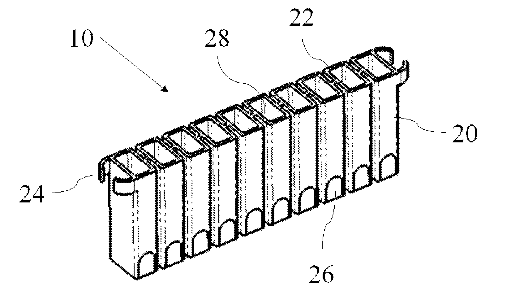
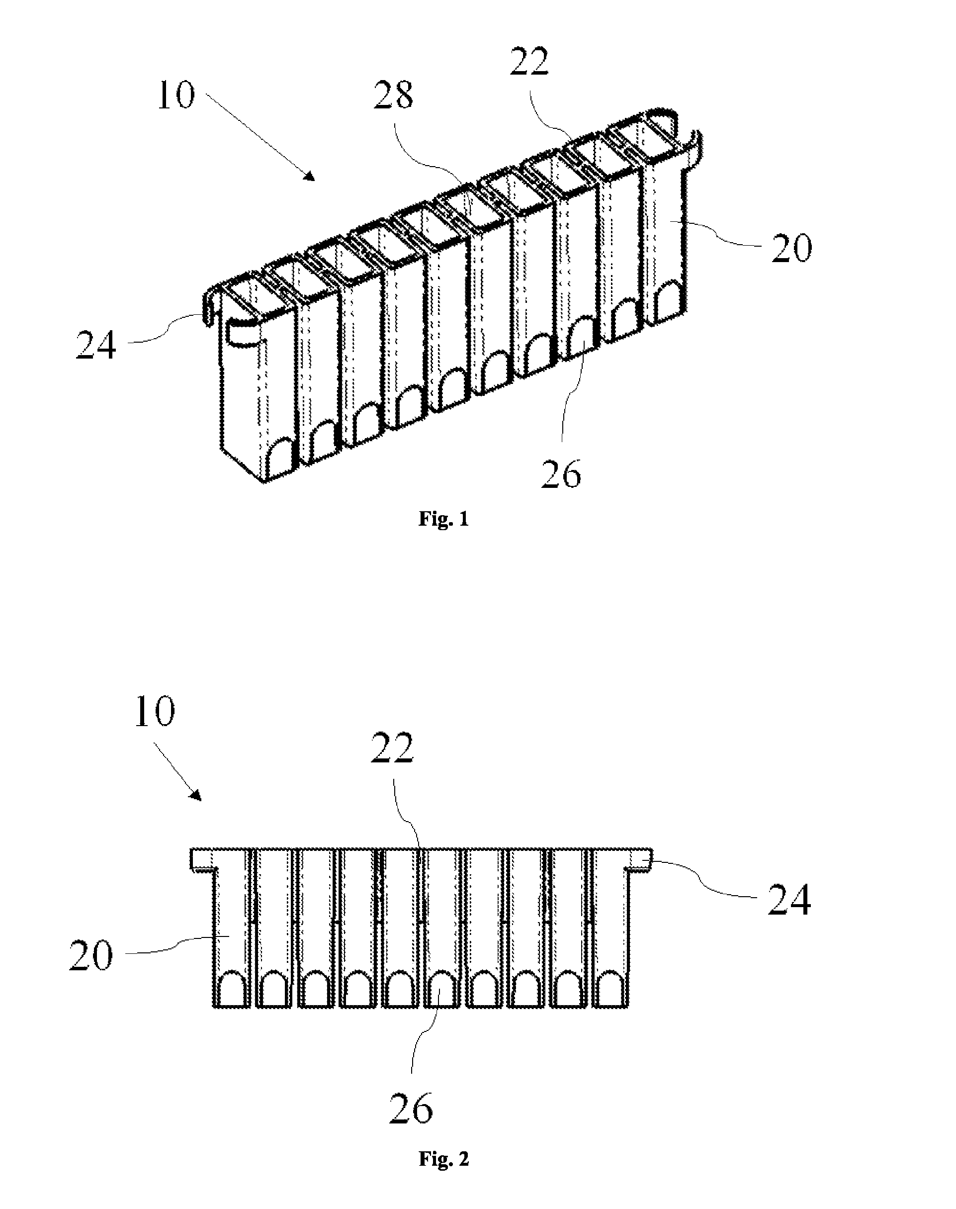
[0021]As illustrated in FIG. 1, the cuvette 10 comprises positions 20, which are in line next to each other. By a cuvette 10 is meant in this context a sample-receiving member with at least one position 20 for receiving the sample and for storage at least during analysis. The position 20 is a tubular vessel wherein a confined sample space 28 for a sample to be analyzed is formed and which is limited by the walls of the vessel. The position 20 has, according to one embodiment, a rounded quadrangular shaped cross-section and is generally shaped such that the sides of the opening of the sample space 28 are considerably shorter than the depth thereof. The sample space 28 can also have another shape. In this context, the direction of the longest side of the sample space 28 of the position 20, i.e. the depth, is called the vertical axis. Correspondingly by a horizontal axis is meant the Cartesian axes orthogonal to the vertical axis.

[0022]The cuvette 10 has, according to one embodiment of...


PUM


Abstract

A cuvette (10) for an automatic analyzing apparatus according to the invention includes at least two positions (20), for each position pair one separating wall (22) connecting the positions (20), and brackets (24), which are at the outermost positions (20) and which guide the cuvette (10) into a curved shape. In a handling method of a cuvette (10) according to the invention a cuvette (10) is transported from its brackets (24) to an incubator (30) and bent into a curved shape. In the method the cuvette (10) is then loaded into an opening (34) of the incubator (30), in which opening (34) it remains by its own spring back factor, until the cuvette (10) is removed from the opening (34) after the analysis.

Description

CROSS-REFERENCE TO RELATED APPLICATIONS[0001]The present application claims priority under 35 USC 119 to Finish Patent Application No. 20085509 filed on May 28, 2008 and PCT Patent Application No. PCT / FI2009 / 050450 filed on May 27, 2009 the entire contents of which are hereby incorporated by reference.BACKGROUND OF THE INVENTION[0002]1. Field of the Invention[0003]The present invention relates to a new type of a reaction vessel, i.e. a cuvette, for usage in automatic analyzers and to a cuvette incubation method. More precisely, the present invention relates to a cuvette and an incubation method according to the preambles of the independent claims.[0004]2. Description of Background Art[0005]As known, disposable and reusable cuvettes have been used in automatic analyzers as individual cuvettes or as sets of cuvettes. Cuvettes are vessels into which a sample to be analyzed and possible other substances to be used in the test are portioned out for the analysis. Reusable cuvettes are cle...

Claims


Application Information

Patent Timeline
IPC IPC(8): B01L3/00
CPCG01N35/025Y10T436/113332Y10T436/25G01N2035/0465G01N21/03G01N35/026G01N21/13B01L3/5025B01L2300/0832B01L2300/0848
Inventor NUOTIO, VESAMAKUNEN, JUHANI
Owner THERMO FISCHER SCI OY
Why Eureka
Try Eureka