
Video imaging system with a camera control unit

a control unit and video imaging technology, applied in the field of camera control units, can solve the problems of time-consuming for users, limited equipment function, and the difference between older and newer equipment, and contribute to the compatibility problems of the ccu and the new equipmen

Inactive Publication Date: 2012-06-12
KARL STORZ IMAGING INC
View PDF51 Cites 24 Cited by
  • Summary
  • Abstract
  • Description
  • Claims
  • Application Information

AI Technical Summary

Benefits of technology

Enables quick and easy access to image data for users, reduces time spent on setting adjustments, and provides universal compatibility with future technologies, allowing for efficient image manipulation and storage without the need for network connections.

Problems solved by technology

This can be quite time consuming for the user, especially when the user is performing multiple procedures during the day and must readjust the settings every time new equipment is used from operating room to operating room.
However, a limitation of existing systems is that they are generally limited to function with equipment that is currently in use and are not provided to seamlessly integrate with newer equipment.
The difference between older and newer equipment may contribute toward compatibility problems between the CCU and the new equipment.
However, current systems do not allow the user to do is manipulate the image(s) / video presented to the user on the display.

Method used


Image

  • Video imaging system with a camera control unit
  • Video imaging system with a camera control unit
  • Video imaging system with a camera control unit

Examples


Embodiment Construction

[0035]Referring now to the drawings, wherein like reference numerals designate corresponding structure throughout the views.

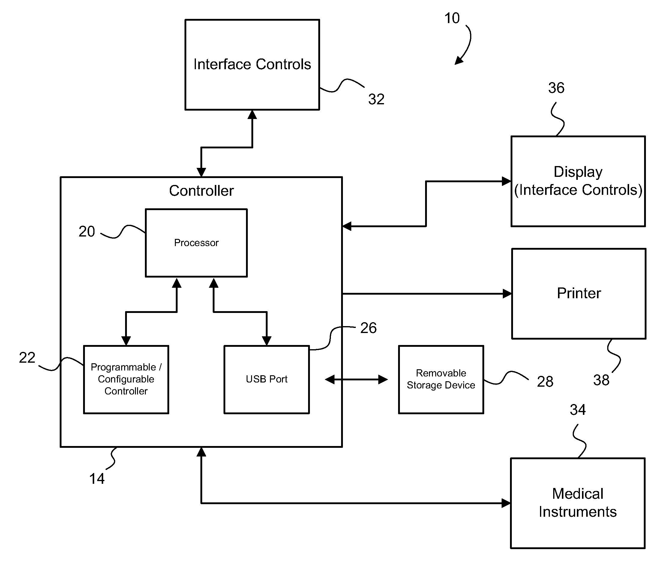
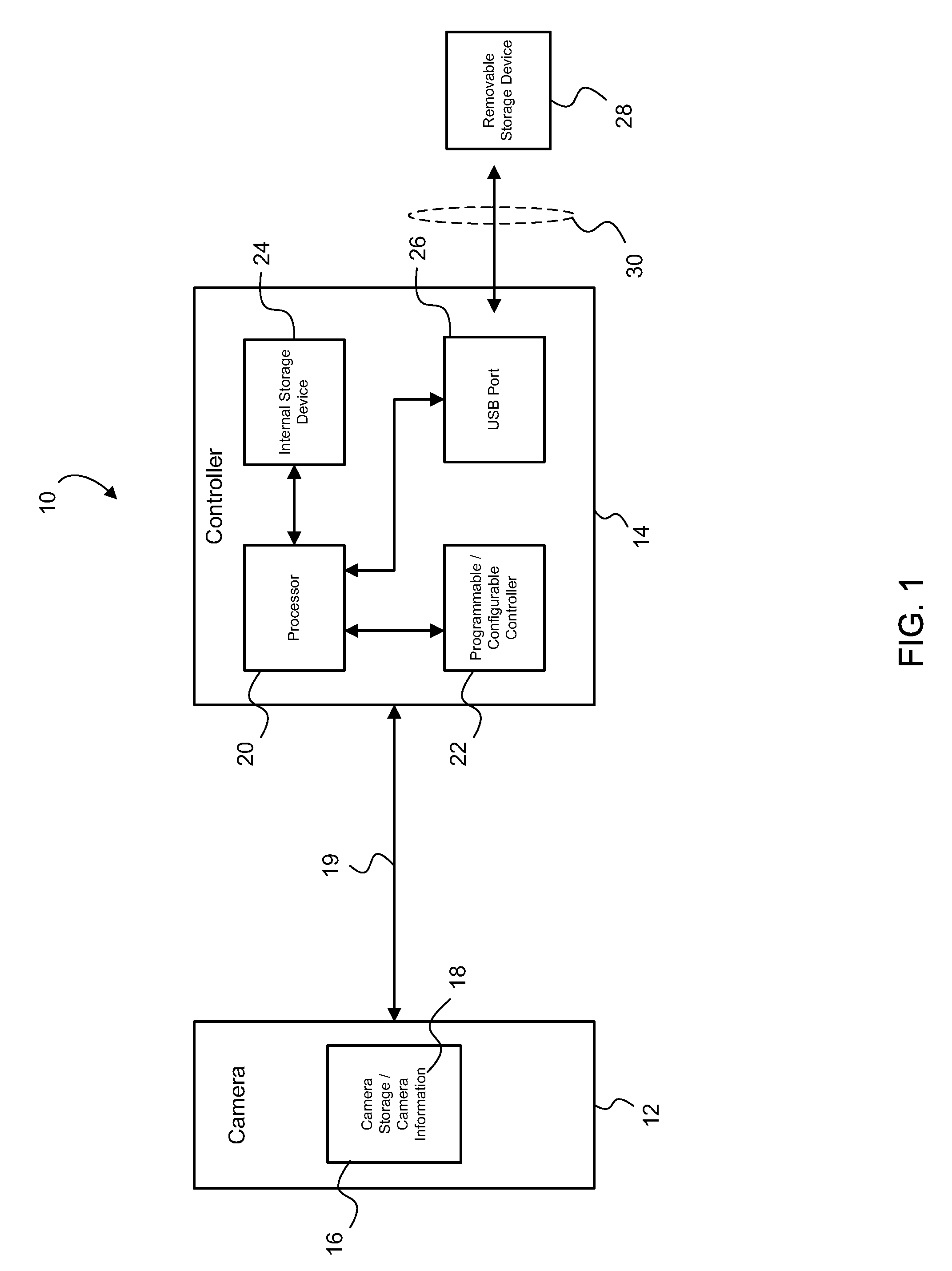
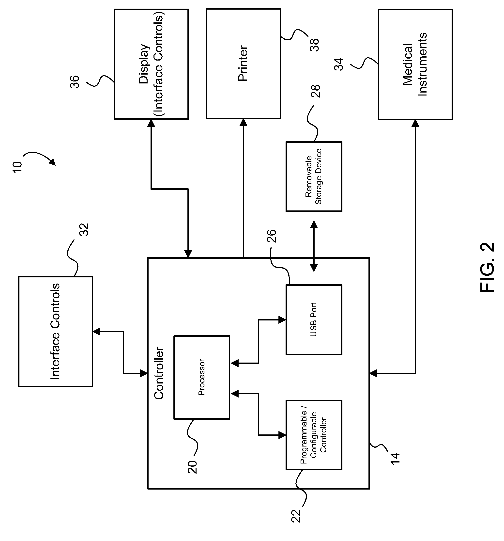
[0036]FIG. 1 is a block diagram illustrating video system 10, which generally includes a camera 12 and a camera control unit (CCU) 14. The camera may include virtually any type of camera that may be used to generate video and / or still frame images. In one embodiment, the camera 12 may be attached to an endoscope for use in a surgical procedure. The camera 12 is coupled to CCU 14 at camera coupling 19 as indicated by the arrow connected between camera 12 and CCU 14 in FIG. 1. It is contemplated that the coupling may comprise either a hard-wired or a wireless coupling. Additionally, the coupling may comprise either an electrical, an optical or a combined electro-optic coupling. For example, the endoscope may be provided with a light source. Alternatively, a light source may be located in the CCU 14 such that the illuminating light is provided to camera 12 via the...


PUM


Abstract

A video imaging system that allows a user to save select image data to a detachable storage device, the image data presented on a display for the user, where the user is provided with various control interfaces for saving and appending information to the saved image data. The detachable storage device also including user settings data that is used to adjust the settings of the camera control unit according to the user preferences.

Description

CROSS REFERENCE TO RELATED APPLICATION[0001]This application is a continuation-in-part of U.S. patent application Ser. No. 10 / 034,273, filed on Dec. 28, 2001, which is a continuation-in-part of Ser. No. 10 / 039,931, filed 11 / 09 / 2001, now U.S. Pat. No. 7,212,227, issued on May 1, 2007.FIELD OF THE INVENTION[0002]The invention relates to a camera control unit capable of processing a video signal from many different types of video cameras and, more particularly, the invention relates to an integrated camera control system that can save images to numerous types of storage devices.BACKGROUND OF THE INVENTION[0003]A camera and a camera control unit (CCU) are generally used in conjunction with each other to capture and process images, whether still frames or video clips. The camera typically includes a charge couple device (CCD) for receiving reflected light and generating an image signal, which is sent to the control unit. The image signal may be sent to the control unit via a hardwired ca...

Claims


Application Information

Patent Timeline
Patent Type & Authority Patents(United States)
IPC IPC(8): A61B1/04H04N5/76H04N25/00
CPCH04N5/232H04N5/23206H04N5/77H04N5/772H04N5/907H04N2005/2255H04N5/781H04N5/775H04N5/765H04N23/555H04N23/661H04N23/617
Inventor AMLING, MARC R.LIETZ, DANIELKYPEROUNTAS, MARIOS
Owner KARL STORZ IMAGING INC
Learn More