Smart Functionality for Discrete Field Devices and Signals

a technology of discrete field devices and signals, applied in the direction of program control, total factory control, instruments, etc., can solve the problems of inefficient deployment of i/o cards and unused i/o channels, terminal blocks, inconvenient updating of field modules, and high cost of project changes. , to achieve the effect of quick and easy updating of field modules

Active Publication Date: 2020-04-02
FISHER-ROSEMOUNT SYST INC
View PDF0 Cites 9 Cited by
  • Summary
  • Abstract
  • Description
  • Claims
  • Application Information

AI Technical Summary

Benefits of technology

[0029]The field module may store a profile including information relevant to commissioning and configuring the field module and any connected field devices, such as a tag unique to the field module itself and / or signal tags unique to the DI and DO channels connected to the field module. Information in the profile can be autosensed by the electronic marshalling apparatus (and, in particular, by a signal characterization component or module connected to the marshaling apparatus), enabling any of the tags in the profile to be assigned or bound to an I / O channel on which the corresponding DI or DO signal exists. These autosensing and binding techniques to autosense a tag of a field module and to automatically update a binding for the tag enable easy and fast reconfiguration and rewiring of the I / O networks.
[0031]A portable device that may be utilized to update the profile of the field module is also described. Generally speaking, the portable device may establish one or more short range communication channels with the field module and use that communication channel to download new information to the profile of the field module. Example short range communication channels include RFID channels, NFC channels, Bluetooth channels, and Wi-Fi direct channels. Helpfully, the portable device enables a person in the field environment to quickly and easily update the field module while in close proximity (e.g., after updating field wiring to add, replace, or remove a channel to a field device) rather than requiring the person to return to a workstation in the back-end environment of the plant. Thus, the portable device enables the person to visually inspect the field module and confirm or reconfirm that information in the updated profile accurately reflects the changes in field wiring, field device connections, or control schemes.

Problems solved by technology

Unfortunately, the design of the I / O network 200 is inflexible and difficult to change after field wiring has been completed, making project changes expensive in terms of labor, time, and material.
This requirement, along with the requirement that each of the I / O cards 156 only supports up to four channels, results in unused and wasted terminal blocks.
Of note, channel limitations associated with the dedicated I / O cards 156 results in inefficient deployment of I / O cards and unused I / O channels, terminal blocks, and associated cabinet space in the marshalling cabinet 150.
This imperfect match between signal requirements for the field devices 152 and the limitations of the I / O cards 156 results in an inefficient deployment of the I / O cards 156.
Consequently, when the controller 158 needs multiple parameters obtained by or associated with the field device 1521 (e.g., to implement the associated control strategy), an I / O channel must be wired for each parameter represented by a DI signal, resulting in multiple wired I / O channels and additional field wiring complexity.
This is problematic because in most plants a significant portion of field device inputs and outputs are configured for discrete signaling.
Generally speaking, this problem with a high ratio of I / O channels to field device variables is less of an issue with smart field devices configured to send or receive analog signals because of the HART® protocol.
On the other hand, “dumb” or “legacy” field devices generally do not include on-board processor(s) and / or on-board memories and generally have no ability to transmit secondary variable values.
Previously, smart commissioning and auto-sensing was not feasible with discrete devices and signals.
Typical discrete devices are “dumb” in that they are not capable of storing information or sending anything via a discrete signal other than a single binary variable value.
Thus, unlike smart field devices configured for messaging via analog signaling (e.g., HART devices), these dumb discrete devices have no way to store or transmit a tag to other devices and consequently are incapable of smart commissioning.
Unfortunately, discrete devices such as limit switches and solenoids constitute a significant number of the devices in many plants.
Notably, such retrofitting efforts would likely encounter challenges due to certain discrete devices (notably solenoids) having (i) significant inductance and consequently a tendency to swamp communication signals, and (ii) significant power requirements that traditional communication protocols (such as HART and other analog signaling protocols) are unable to meet.
In some implementations, however, the power received from the channel 282 may be insufficient to power every connected to DO, particularly those having high power requirements (e.g., solenoids).
This auto-sensing function saves technicians from having to manually identify hardware addresses and manually create bindings to the appropriate tags, a process that is prone to human error and that creates challenges if changes in field wiring are necessary.
By contrast, manual commissioning is error prone and requires significant time and effort from technicians who not only have to spend time rewiring, but who rely on manually kept records that may not be updated.
As another example, a technician may simply update a binding for the device with an incorrect hardware address, making it impossible for other devices to reference the device via its unique tag.
Further, Manchester encoding is self-clocking and thus requires clock recovery from the signal when the signal is decoded.
The detailed description is to be construed as exemplary only and does not describe every possible embodiment because describing every possible embodiment would be impractical, if not impossible.

Method used


Image

  • Smart Functionality for Discrete Field Devices and Signals
  • Smart Functionality for Discrete Field Devices and Signals
  • Smart Functionality for Discrete Field Devices and Signals

Examples


Embodiment Construction

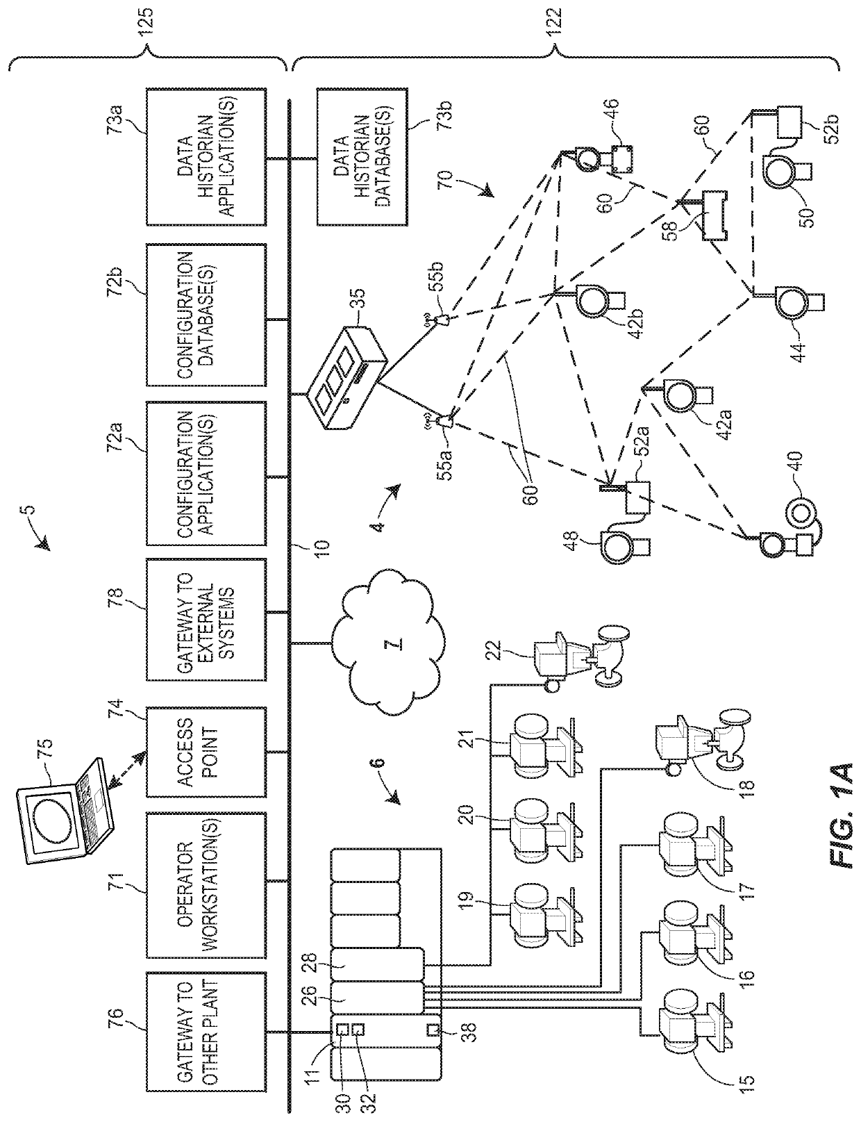
[0048]As discussed above, a process plant, process control system, or process control environment that, when on-line, operates to control one or more industrial processes in real-time may be commissioned utilizing one or more of the novel smart commissioning techniques, systems, apparatuses, components, devices, and / or methods described herein. The process plant, when commissioned and operating on-line, includes one or more wired or wireless process control devices, components, or elements that perform physical functions in concert with a process control system to control one or more processes executing within the process plant. The process plant and / or process control system may include, for example, one or more wired communication networks and / one or more wireless communication networks. Additionally, the process plant or control system may include centralized databases, such as continuous, batch, asset management, historian, and other types of databases.

[0049]Below, the descripti...


PUM


Abstract

A set of discrete input / output (I / O) channels for one or more field devices may be grouped, organized, and connected to a field module device, which may connect to an electronic marshalling apparatus in a marshalling cabinet via an I / O channel. The field module acts as an intermediary, decoding messages received via the I / O channel to identify commands for discrete output (DO) channels that are then forwarded appropriately. The field module may also receive variable values carried by signals on discrete input (DI) channels and encode the values to a message that may be transmitted to the marshalling apparatus and controller, thus making the variable values on the DI channels available to the controller. The field module may store a profile including information that facilitates various smart commissioning techniques, including autosensing of tags, automatic tag binding, and automatic configuration of a control element corresponding to the field module.

Description

TECHNICAL FIELD[0001]The present disclosure relates generally to process plants and process control systems, and more particularly, to imparting smart functionality on discrete elements in a process plant.BACKGROUND[0002]Distributed process control systems, such as distributed or scalable process control systems like those used in power generation, chemical, petroleum, or other processes, typically include one or more process controllers communicatively coupled to each other, to at least one host or operator workstation via a process control network and to one or more field devices via analog, digital or combined analog / digital buses.[0003]The field devices, which may be, for example, valves, valve positioners, switches and transmitters (e.g., temperature, pressure, and flow rate sensors), perform functions within the process or plant such as opening or closing valves, switching devices on and off, and measuring process parameters.[0004]The process controllers, which are typically l...

Claims


Application Information

Patent Timeline
Patent Type & Authority Applications(United States)
IPC IPC(8): G06F1/16G06F1/26H04W76/10
CPCH04W76/10G06F1/1698G06F1/26G05B19/4183G05B2219/32252Y02P90/02G05B19/4185G05B19/41845G05B19/0423
Inventor LAW, GARY K.BURR, KENT A.
Owner FISHER-ROSEMOUNT SYST INC
Why Eureka
Try Eureka