Head suspension

a head and sleeve technology, applied in the direction of maintaining the alignment of the head carrier, recording information storage, instruments, etc., can solve the problems of increasing the size of the attaching part, piezoelectric elements, and little or no filler in the adhesive, so as to increase the degree of design freedom, the size of the fitting part is minimized, and the space is wide.

Active Publication Date: 2012-06-12
NHK SPRING CO LTD
View PDF18 Cites 40 Cited by
  • Summary
  • Abstract
  • Description
  • Claims
  • Application Information

AI Technical Summary

Benefits of technology

[0015]This aspect of the present invention forms the electric insulating layer between the piezoelectric element and the fitting part by vapor-depositing and polymerizing electrically insulative high polymer materials on the fitting part. The electric insulating layer stably maintains a designed electric insulating characteristic and is uniform in thickness without regard to the shape of the fitting part. This aspect eliminates the need of a relatively wide space including a designing allowance to be secured between the piezoelectric element and the fitting part.
[0016]Namely, this aspect allows the size of the fitting part to be minimized according to the size of the piezoelectric element. As a result, the head suspension of this aspect increases the degree of designing freedom and meets the need for miniaturization.

Problems solved by technology

An important issue for the head suspension employing the dual actuator system is how to mount the piezoelectric elements on the head suspension.
According to this related art, there will be a situation that there is little or no granular filler in the adhesive between the piezoelectric elements and the attaching part.
This results in increasing the size of the attaching part and leaving a miniaturization request for head suspensions unfulfilled.

Method used


Image

  • Head suspension
  • Head suspension
  • Head suspension

Examples


Embodiment Construction

[0024]A head suspension according to an embodiment of the present invention will be explained in detail with reference to the drawings.

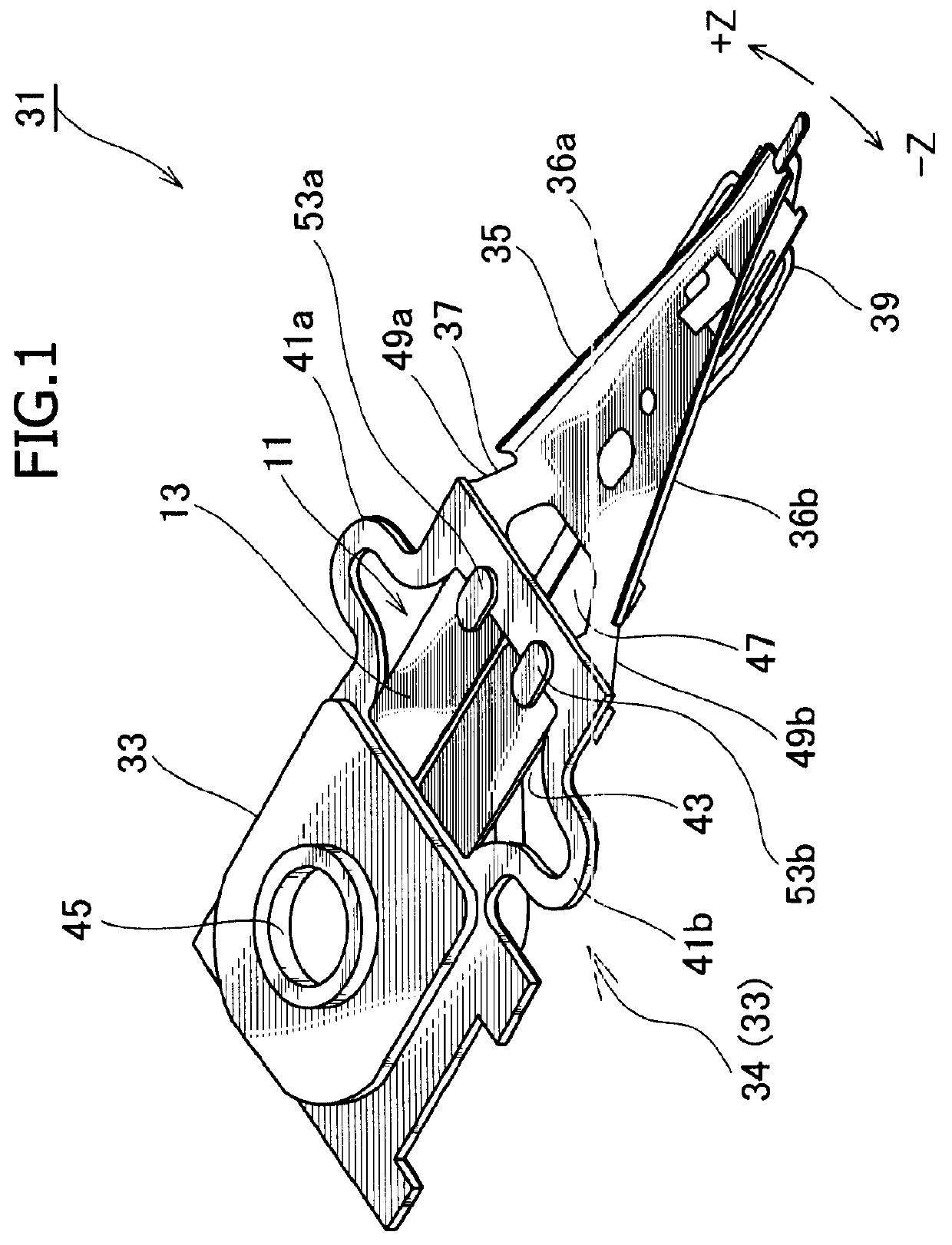
[0025]FIG. 1 is a perspective view illustrating the head suspension 31 according to an embodiment of the present invention.

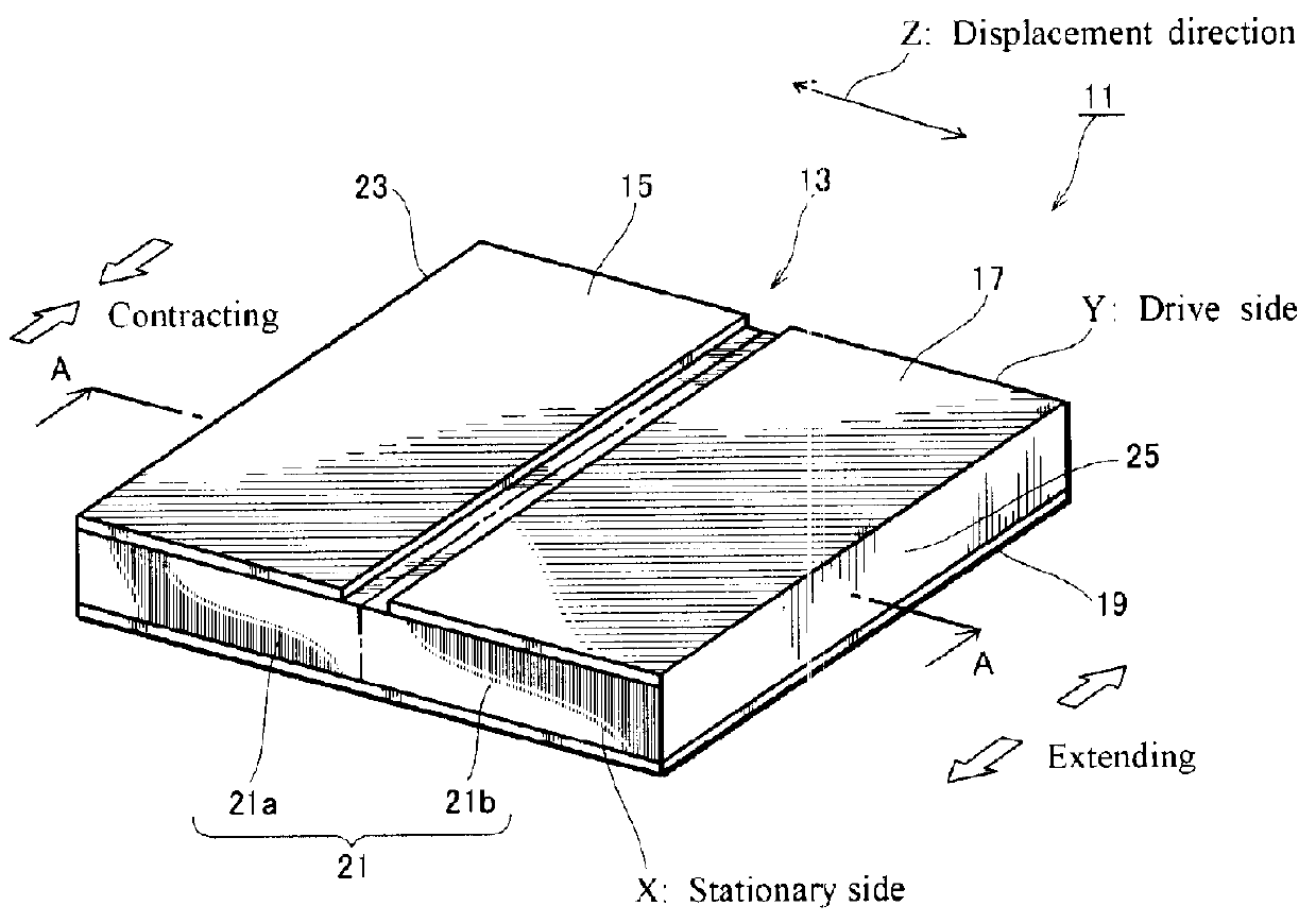
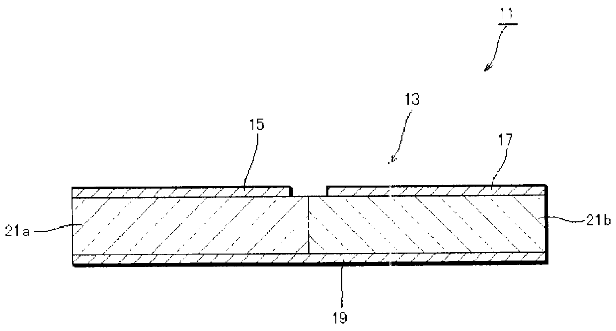
[0026]The head suspension 31 includes a piezoelectric actuator 11 consisting of a piezoelectric element 13 that deforms in response to a voltage applied thereto, a base plate 33 (corresponding to the base stipulated in the claims), a load beam 35, a connection plate 37 functioning as a hinge, and the like. The base plate 33 has an opening 43 (corresponding to the fitting part stipulated in the claims) into which the piezoelectric element 13 is fitted. The piezoelectric element 13 deforms in response to an applied voltage, to move a front end of the load beam 35 in a sway direction, i.e., a widthwise direction of the head suspension 31.

[0027]The base plate 33 is made of, for example, a stainless steel thin plate having a thickness...


PUM

PropertyMeasurementUnit
thicknessaaaaaaaaaa
thicknessaaaaaaaaaa
thicknessaaaaaaaaaa

Abstract

A head suspension 31 has a piezoelectric element 13 that deforms in response to a voltage applied thereto, a base plate 33 having an opening 43 into which the piezoelectric element 13 is fitted, and a load beam 35 that is fixed to the base plate 33 so that a front end of the load beam 35 moves in a sway direction according to the deformation of the piezoelectric element 13. The head suspension 31 includes an electric insulating layer 51 formed at the opening 43 by vapor-depositing and polymerizing electrically insulative high polymer materials at the opening 43. The piezoelectric element 13 is fitted into the opening 43 through at least the electric insulating layer 51. The head suspension 31 satisfies a miniaturization requirement.

Description

BACKGROUND OF THE INVENTION[0001]1. Field of the Invention[0002]The present invention relates to a head suspension having a piezoelectric element that deforms in response to a voltage applied thereto and is fitted through at least an electric insulating layer to a fitting part of a base of the head suspension.[0003]2. Description of Related Art[0004]Small-sized, precision information devices are rapidly advancing and needs for micro-actuators capable of conducting positioning control for very small distances in such devices are also increasing. The devices that particularly need such micro-actuators include optical systems for correcting focuses and inclination angles, ink jet printers for controlling ink heads, and magnetic disk drives for controlling magnetic heads.[0005]The magnetic disk drives have an urgent issue to solve, i.e., increasing storage capacity. The storage capacity of a magnetic disk drive will increase if the storage capacity of each magnetic disk in the magnetic ...

Claims


Application Information

Patent Timeline
Patent Type & Authority Patents(United States)
IPC IPC(8): G11B21/10G11B5/596G11B21/21
CPCG11B5/4826G11B5/4873G11B5/5552G11B5/596
Inventor NOJIMA, AKIRA
Owner NHK SPRING CO LTD
Why Eureka
Try Eureka