Modular hand guard assembly

a module and hand guard technology, applied in weapon parts, butts, weapons, etc., can solve the problems of not providing enough room along the interface rails to allow multiple accessories, and most other accessories cannot be mounted on the upper rail, so as to reduce interference with other accessories

Active Publication Date: 2012-06-19
SWAN RICHARD E
View PDF57 Cites 112 Cited by
  • Summary
  • Abstract
  • Description
  • Claims
  • Application Information

AI Technical Summary

Benefits of technology

[0012]It is therefore an object of the present invention to provide an integration system that includes additional mounting interfaces for accessories that reduces interference with other accessories already residing on the hand guard. It is a further object of the present invention to provide a modular hand guard assembly that includes an easily removed section that allows mounting of an accessory on the forward portion of the hand guard that positions the accessory out of the way of the various sighting devices already positioned on the hand guard. It is still a further object of the present invention to provide a modular and integrated switching and control system for activating the various weapon accessories from a common location.

Problems solved by technology

The difficulty is that many end users of this weapon system have multiple sighting devices in addition to a variety of lighting devices, accessory handgrips, etc. that are selectively attached to the weapon 2 for enhanced use of the weapon.
One of the continuing drawbacks of the prior art mounting systems is that they still do not provide enough room along the interface rails to allow multiple accessories to be used in conjunction with one another.
Often, since one of the primary accessories used on the upper rail is an optical sight, most other accessories can't be mounted on the upper rail forward of the sight, because they end up blocking the sight.

Method used


Image

  • Modular hand guard assembly
  • Modular hand guard assembly
  • Modular hand guard assembly

Examples


Embodiment Construction

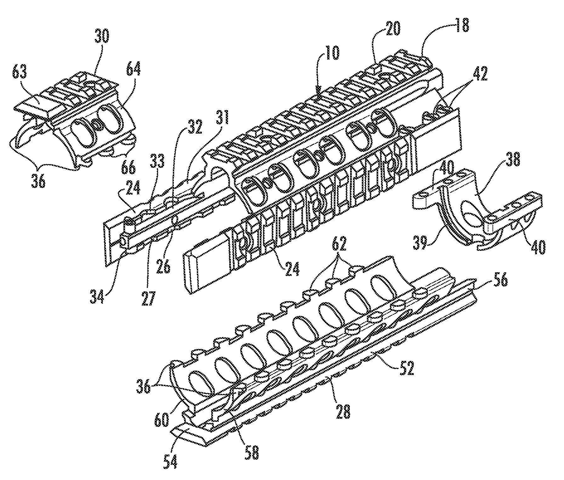
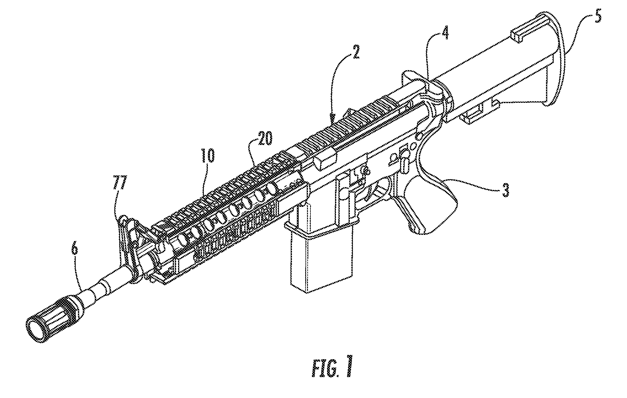
[0028]Now referring to the drawings, the modular hand guard system is shown and generally indicated at 10 in the figures. As can be seen, the modular hand guard assembly 10 of the present invention generally includes an upper hand guard 11, a clamp 38 for affixing the upper hand guard 11 to the firearm 2, a lower hand guard 28 and a switching system 80.

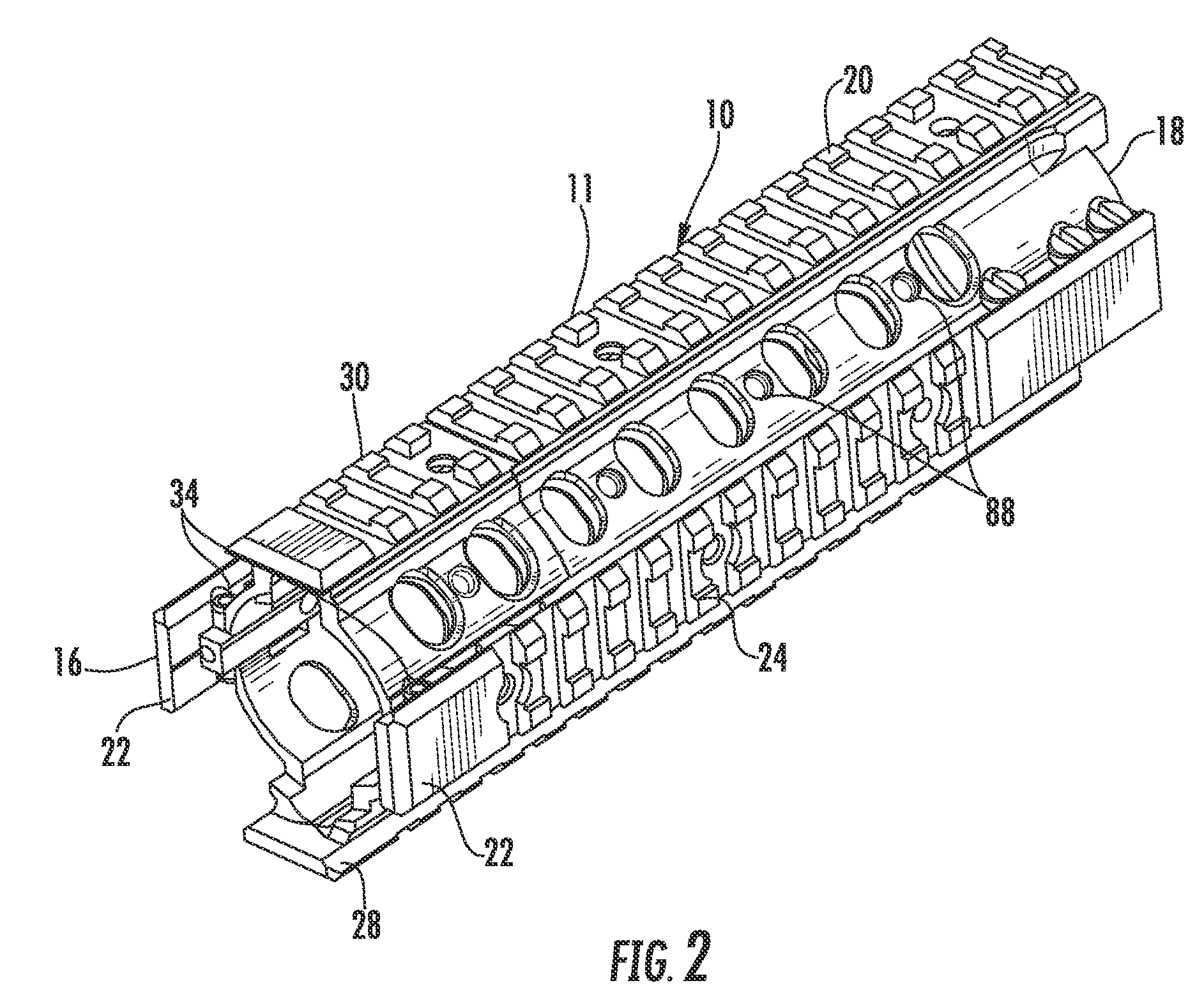
[0029]Turning now to FIGS. 1 and 2, the upper hand guard 11 is the primary structural element that supports the hand guard system 10 relative to the firearm 2. The upper hand guard 11 is formed generally as the upper half of a tubular enclosure that is configured to encircle the barrel 6 of the firearm 2 when in a mounted position. The upper hand guard 11 has a forward end 16 and a rearward end 18 and a standard dovetail rail 20 extending longitudinally between the forward end 16 and the rearward end 18. The upper hand guard 11 has left and right side walls 22 that extend generally outwardly and downwardly from the dovetail rail 20 fo...


PUM


Abstract

A modular hand guard assembly serves both as a hand guard system and as an integrated interface system for mounting various weapon accessories and attachments thereto. The modular hand guard assembly includes a removable forward rail section that can be removed from the forward portion of the hand guard to provide for the installation of additional weapon accessories such as lights, optics or lasers in highly a desirable forward location adjacent to the barrel of the weapon. The modular hand guard assembly further includes a removable lower hand guard to provide access to the barrel of the firearm and an integrated modular switching and control system for use in connection with the various powered accessories mounted thereto.

Description

CROSS-REFERENCE TO RELATED APPLICATIONS[0001]This application is related to and claims priority from earlier filed U.S. Provisional Patent Application No. 61 / 144,470, filed Jan. 14, 2009 and earlier filed U.S. Provisional Patent Application No. 61 / 144,471, filed Jan. 14, 2009. This application is also a continuation-in-part of pending U.S. application Ser. No. 29 / 339,647 filed Jul. 3, 2009, which is a division of issued U.S. Pat. No. D606155, filed Jan. 14, 2009 and issued Dec. 15, 2009.BACKGROUND OF THE INVENTION[0002]The present invention relates generally to a modular hand guard assembly for firearms. More specifically, the present invention relates to a modular assembly that is affixed to a firearm that facilitates integration and mounting of additional equipment onto a firearm.[0003]In the general field of combat and commercial weaponry, numerous add-on enhancements have become available for attachment to standard firearms thereby significantly upgrading the capability of the f...

Claims


Application Information

Patent Timeline
Patent Type & Authority Patents(United States)
IPC IPC(8): F41C23/16
CPCF41C23/16F41C27/00F41G11/003
Inventor SWAN, RICHARD E.
Owner SWAN RICHARD E
Why Eureka
Try Eureka