Control device for mobile body

a control device and mobile body technology, applied in the direction of programme control, instruments, optical radiation measurement, etc., can solve the problems of frequently overshooting or undershooting the desired posture of the robot body, and achieve the effect of smooth elimination of the deviation of the actual base body postur

Active Publication Date: 2012-06-19
HONDA MOTOR CO LTD
View PDF31 Cites 21 Cited by
  • Summary
  • Abstract
  • Description
  • Claims
  • Application Information

AI Technical Summary

Benefits of technology

[0010]An object of the present invention is, therefore, to provide a control device for a mobile body which is capable of smoothly eliminating a deviation of an actual base body posture from a desired base body posture. When a mobile body, such as a legged mobile robot, travels while moving its base body up and down, the control device is capable of determining a required manipulated variable that makes it possible to smoothly eliminate an actual posture deviation from a desired posture of the base body, thus smoothly eliminating the deviation of the base body posture on the basis of the required manipulated variable while restraining the occurrence of an overshoot or an undershoot at the same time.
[0031]Thus, the first aspect and the second aspect of the invention make it possible to determine a required manipulated variable that enables smooth elimination of a deviation of the actual posture of the body from a desired posture while restraining the occurrence of an overshoot or an undershoot.
[0032]Further, according to the first aspect of the invention, the required manipulated variable determined as described above is supplied to the operation control device. At this time, the operation control device performs the operation control of the mobile body so as to additionally apply the additional external force defined by the required manipulated variable to the mobile body while causing the actual motion of the mobile body to follow the desired motion. More specifically, the operation control device drives an actuator of the mobile body so as to additionally apply the additional external force defined by the required manipulated variable to the mobile body while causing the actual motion of the mobile body to follow the desired motion. This makes it possible to additionally apply an external force that brings a state amount deviation close to zero to the actual mobile body, thus permitting smooth elimination of the deviation of a real posture (actual posture) of the base body from the desired posture.
[0033]Further, according to the second aspect of the invention, the required manipulated variable determined as described above is supplied to the desired motion determining device. At this time, the desired motion determining device determines a model manipulation external force to be added to the desired external force on the dynamic model on the basis of the determined required manipulated variable. Then, the desired motion determining device determines the desired motion such that the time series of a desired inertial force defined by the determined up-and-down-direction inertial force parameter is satisfied on the dynamic model while applying the external force obtained by adding the determined model manipulation external force to the desired external force to the mobile body on the dynamic model. Then, the operation control device carries out the operation control of the mobile body on the basis of at least the determined desired motion. More specifically, the actuator of the mobile body is driven such that the actual motion of the mobile body follows the determined desired motion. This makes it possible to generate the desired motion while additionally applying an external force that brings a state amount deviation close to zero to the mobile body on the dynamic model, thus permitting smooth elimination of the deviation of a real posture (actual posture) of the base body from the desired posture.
[0049]According to the sixth aspect of the invention, the arithmetic processing for determining the first gain coefficient and the second gain coefficient is constructed to converge to zero the predetermined linearly coupled value of the state amount deviation at the predetermined time and the temporal change rate thereof calculated according to the state equation from the observed value of the state amount deviation at the current time and the temporal change rate thereof, the time series of the desired inertial force in the period from the current time to the predetermined time, and the time series of the inertial force of the mobile body or the base body in the period of one cycle of the reference motion. This arrangement makes it possible to determine the first gain coefficient and the second gain coefficient by accurately reflecting the time series of the desired inertial force in the period from the current time to the predetermined time and the time series of the inertial force of the mobile body or the base body in the reference motion serving as the convergence target of the time series of the desired inertial force (more specifically, the arrangement makes it possible to smoothly converge the state amount deviation to zero while converging the motion of the mobile body to the reference motion in a situation wherein the actual inertial force is generated according to the time series of the desired inertial force).

Problems solved by technology

However, it has been found that, in the case of a gait involving vertical motions of the body, as in the case where the robot runs, if the posture of the robot body is feedback-controlled on the basis of the operational moment determined by the PD law using the fixed values of the gain coefficients as described above, then the actual posture of the robot body frequently overshoots or undershoots a desired posture due to a change in the inertial force produced in the body (consequently the robot) caused by up and down motions of the body.

Method used


Image

  • Control device for mobile body
  • Control device for mobile body
  • Control device for mobile body

Examples


Embodiment Construction

[0089]The following will describe an embodiment of the present invention by taking a bipedal mobile robot as an example of a mobile body.

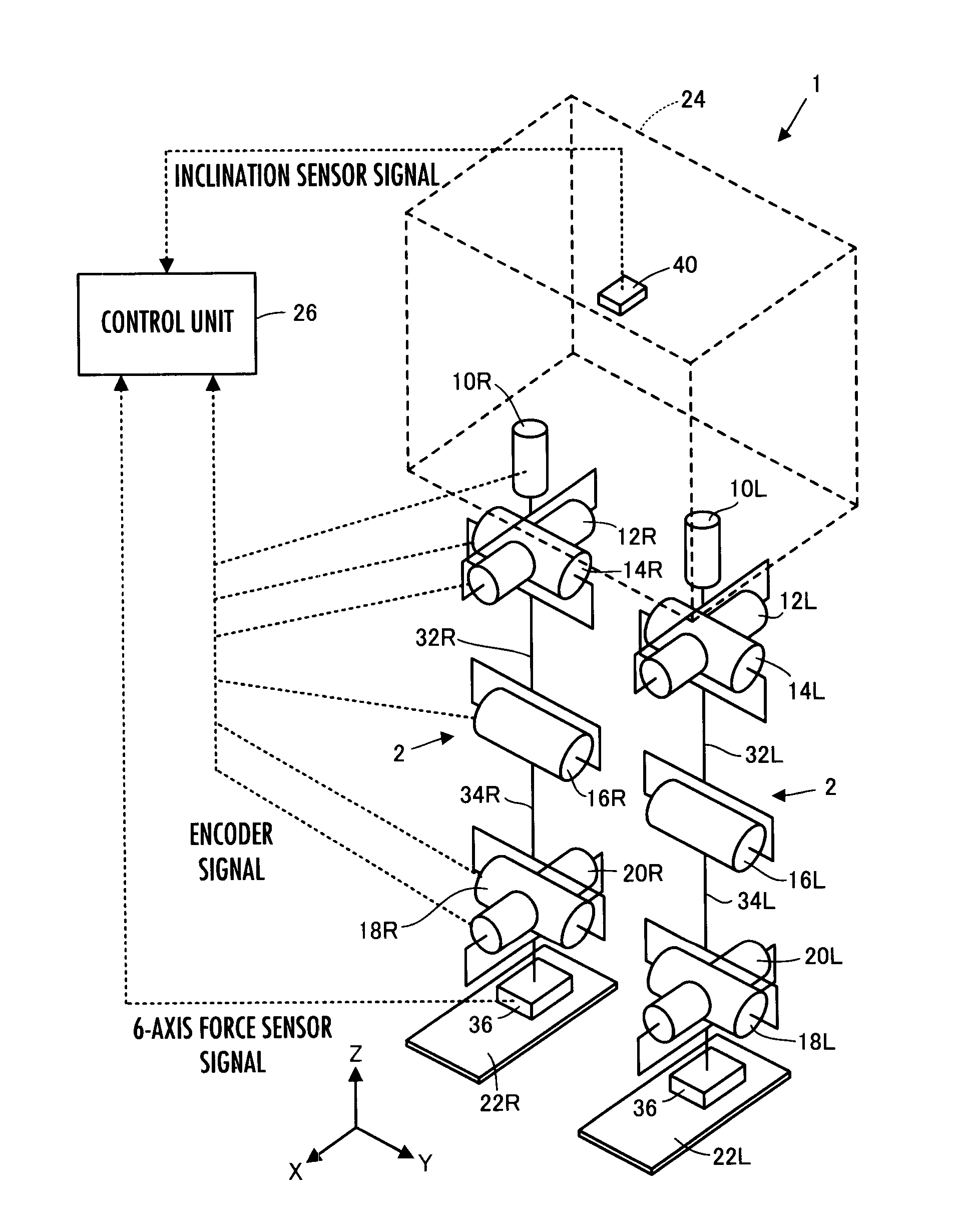
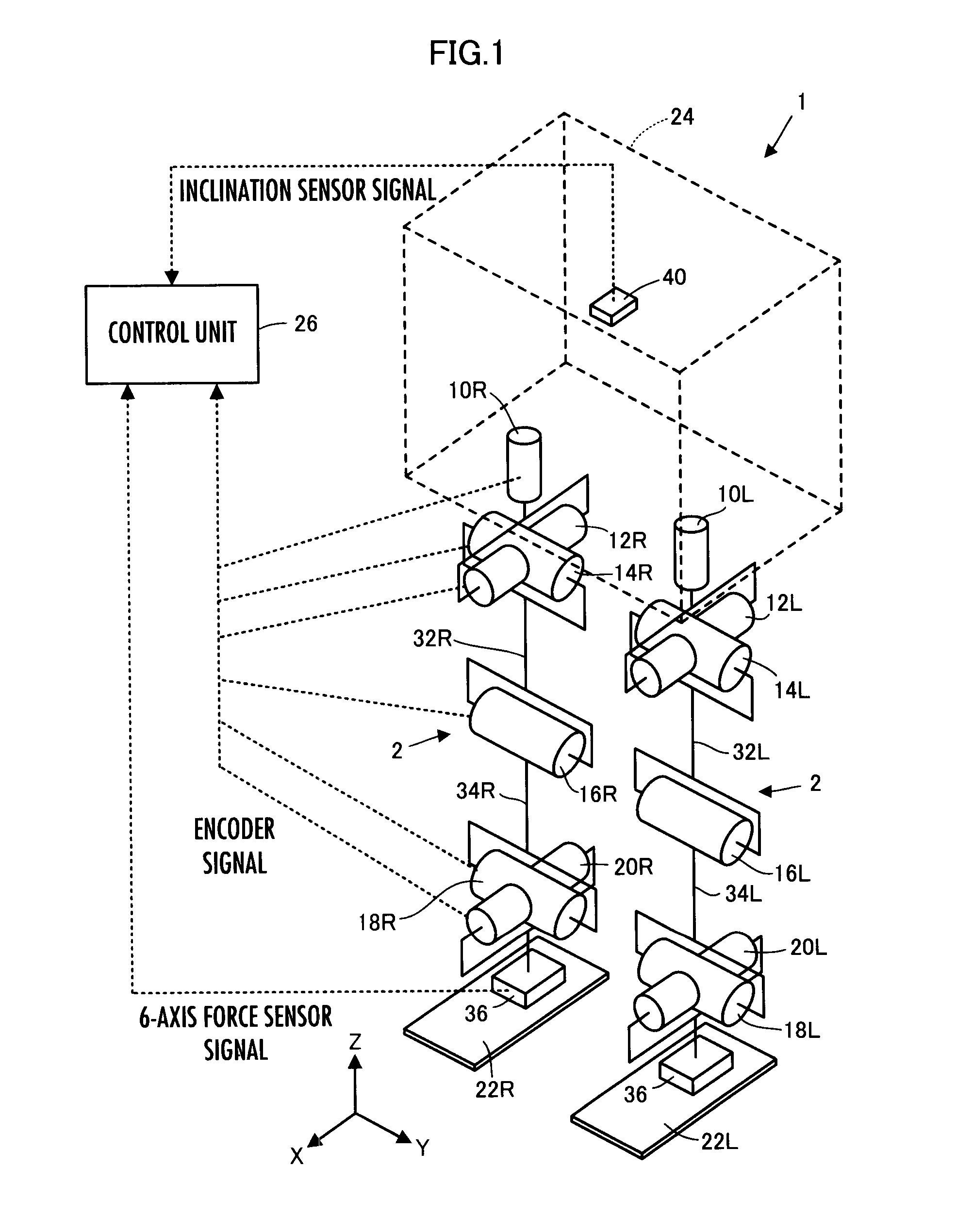
[0090]As illustrated in FIG. 1, a bipedal mobile robot 1 (hereinafter referred to simply as the robot 1) according to the present embodiment has a body 24 as a base body and a pair of right and left legs (leg links) 2, 2 interposed between the body 24 and a floor as a moving mechanism for moving the body 24 on a floor surface.

[0091]The body 24 is connected to the proximal end portions (upper end portions) of the two legs 2, 2 through the intermediary of a waist joint (hip joint), which will be discussed later, and is supported above the floor surface by one or both of the legs 2, 2 that are in contact with the ground.

[0092]The two legs 2, 2 share the same construction and each thereof has six joints. The six joints are a joint 10R or 10L for turning a waist (hip) (for the rotation in the yaw direction relative to the body 24), a joint 12R or 12L fo...


PUM


Abstract

A control device for a mobile body makes it possible to smoothly correct the deviation of an actual posture of a base body of a mobile body, which travels with the base body thereof moving up and down, from a desired posture of the base body while restraining an overshoot or an undershoot from occurring. To determine a required manipulated variable according to a feedback control law in order to converge a state amount deviation related to the posture of the base body of the mobile body to zero, the feedback gain of the feedback control law is determined by using the time series in a period from current time to predetermined time in the future in the time series of a desired inertial force of the mobile body or the base body. The required manipulated variable is determined by the calculation of the feedback control law on the basis of the determined feedback gain and an observed value of the state amount deviation.

Description

BACKGROUND OF THE INVENTION[0001]1. Field of the Invention[0002]The present invention relates to a control device for a mobile body, such as a legged mobile robot.[0003]2. Description of the Related Art[0004]As a mobile body provided with a base body and a moving mechanism which moves the base body on a floor surface, a legged mobile robot, for example, is generally known. In the legged mobile robot, its legs correspond to the moving mechanism and its body corresponds to the base body.[0005]In the legged mobile robot, for example, as a technique for enhancing the stability of a posture of the robot, the technique disclosed in Published PCT International Applications WO2003 / 061917 (hereinafter referred to as patent document 1) or the like has been previously proposed by the applicant of the present application. According to the technique, a state amount deviation, which is a deviation of an actual posture of the body of a robot from a desired posture, is observed. Then, an operationa...

Claims


Application Information

Patent Timeline
Patent Type & Authority Patents(United States)
IPC IPC(8): G05B21/00
CPCB62D57/032
Inventor YOSHIIKE, TAKAHIDETAKENAKA, TORUMATSUMOTO, TAKASHI
Owner HONDA MOTOR CO LTD
Why Eureka
Try Eureka