Dual acting locking jar

a double-action, locking technology, applied in the direction of fluid removal, drill bits, borehole/well accessories, etc., can solve the problem of mechanical triggers and hydraulic design time delays, and achieve the effect of eliminating preventing the tool from inadvertently jarring on the surface, and reducing the need for safety clamps

Active Publication Date: 2012-06-26
EVANS ENG & MFG INC
View PDF11 Cites 18 Cited by
  • Summary
  • Abstract
  • Description
  • Claims
  • Application Information

AI Technical Summary

Benefits of technology

[0006]This configuration has many advantages over the existing art. The spring can be configured to define a minimum jarring load. This prevents the tool from inadvertently jarring on the surface and eliminates the need to use a safety clamp when racking the tool with drill collars. All of the high pressure is confined to the area between the pressure pistons so that all the seals that are exposed to well bore fluid are balanced with hydrostatic pressure. The collets and spring give a well defined neutral position. This configuration only requires one spring. This design has a hydraulic time delay but triggers mechanically.
[0007]According to another embodiment of the invention, the jar may be mechanically triggered only without the hydraulic time delay by allowing for free movement of the pistons within the housing.

Problems solved by technology

This design has a hydraulic time delay but triggers mechanically.

Method used


Image

  • Dual acting locking jar
  • Dual acting locking jar
  • Dual acting locking jar

Examples


Embodiment Construction

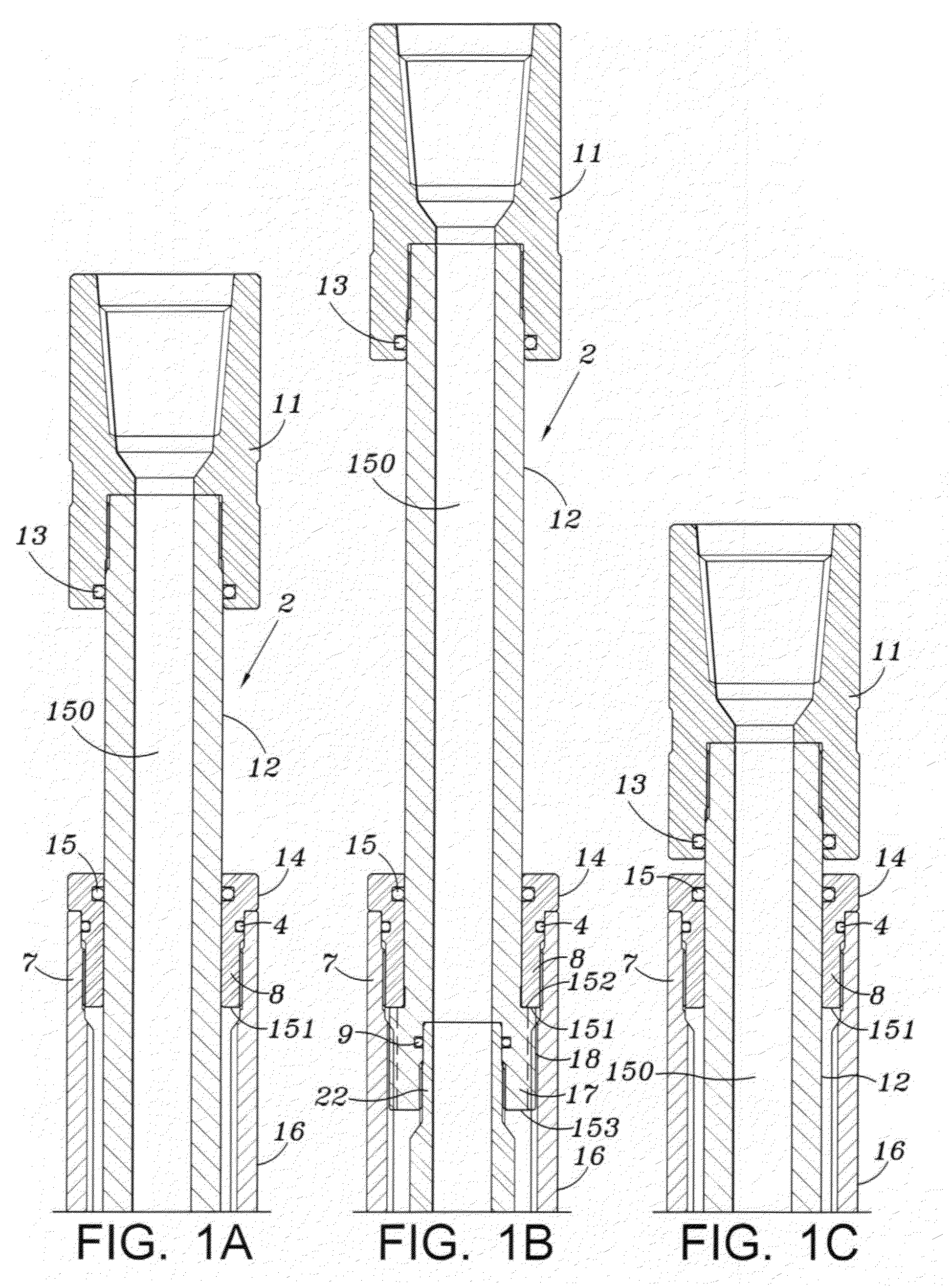
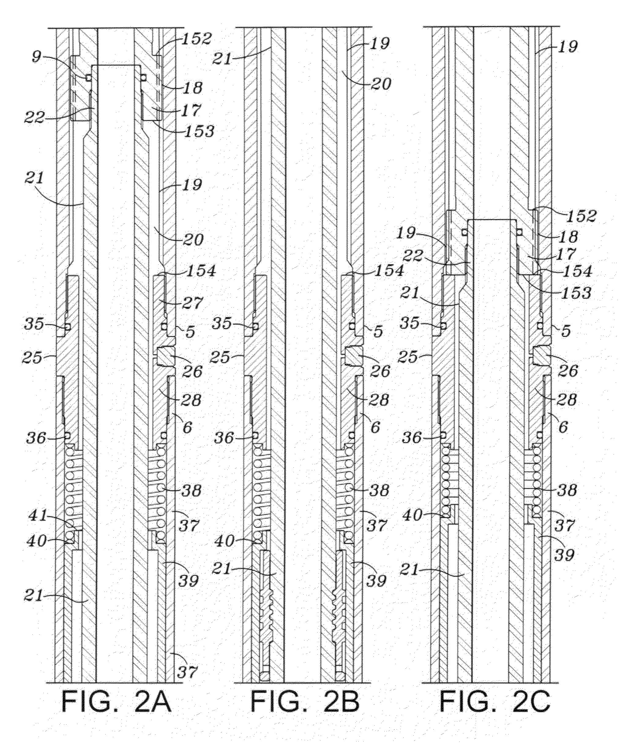
[0014]Referring to FIGS. 1A-5A, an embodiment of the invention includes an outer housing comprising several portions. These include a sealing cap 14, a proximal portion 16, a first filling sub 28, a proximal trigger sleeve housing 37, spring housing 68, distal trigger sleeve housing 99, a second filling sub 120, a floating balance piston housing 125 and distal portion 127 which includes threads 129 for connection to a distal portion of the work string.

[0015]The various portions of the housing are secured together by any known method. In one embodiment, the portions are secured together by male and female threaded segments for example 7, 8 for the sealing cap 14 and proximal portion 16 of the housing. The first filling sub housing portion 28 has externally threaded stubs 27 and 28 that receive internally threaded portions 5 and 6 of proximal portion 16 and trigger sleeve housing portion 37. Trigger sleeve housing portion 37 is externally threaded at 66 to receive an internally thread...


PUM


Abstract

A double action locking jar is operable to provide a jarring force in an upward or downward direction. A pair of pressure pistons form a pressure chamber in which a Belleville spring stack is located. A metering orifice in one of the pistons serves to provide a delay mechanism for release of a mandrel within the housing. Two collets are located within the housing for mechanically releasing the mandrel when a tension or compression force is applied to the mandrel. The jar may be mechanically actuated only by allowing the pistons to freely move within the housing without hydraulic resistance.

Description

BACKGROUND OF INVENTION[0001]1. Field of Invention[0002]This invention is directed to a work string jar which is capable of applying an upward or downward jarring force on a work string used in oil or gas wells.[0003]2. Description of Related Art[0004]Double acting jars are known in the prior art however they have certain drawbacks. A known double acting jar is disclosed in U.S. Pat. No. 5,624,001. This jar requires two sets of Belleville spring stacks which add to the complexity and length of the jar. The high pressure seals within the tool are exposed to the drilling mud which can cause premature failure due to the corrosive and abrasive nature of the drilling mud. Furthermore each of the pressure pistons requires an orifice and a check valve. Also this prior art jar does not include a trigger sleeve which reduces wear on the collet and release mechanism.SUMMARY OF THE INVENTION[0005]A sealed double acting jar with a floating piston to balance the interior fluid with hydrostatic p...

Claims


Application Information

Patent Timeline
Patent Type & Authority Patents(United States)
IPC IPC(8): E21B4/14
CPCE21B31/1135
Inventor EVANS, ROBERT W.
Owner EVANS ENG & MFG INC
Why Eureka
Try Eureka