Camera dolly

a dolly and camera technology, applied in the field of dolly, can solve the problems of loss of productivity in filming with the camera, damage to camera equipment, etc., and achieve the effect of limiting the overall reaction of the wheel assembly and preventing derailmen

Inactive Publication Date: 2012-06-26
WOOD DENNIS
View PDF30 Cites 18 Cited by
  • Summary
  • Abstract
  • Description
  • Claims
  • Application Information

AI Technical Summary

Benefits of technology

[0011]By providing pivot assemblies which permit pivotal movement of the wheels about both a vertical axis and a horizontal axis perpendicular to the rolling direction of the wheels, the wheel assemblies are permitted an additional degree of freedom for rocking in a forward and rearward direction relative to the rolling direction to ensure that most of the wheels of the wheel assemblies remain in contact with the respective rails at all times so as to reduce the likelihood of derailment.
[0013]By further arranging each of the wheels to be spaced in a longitudinal direction relative to wheels of the opposing row of wheels within each wheel assembly, even when bumps or hilly areas occur in the track, only one wheel is affected by the bump so as to limit the overall reaction of the wheel assembly and thus further discourage derailment.

Problems solved by technology

The wheel assemblies are typically pivotally supported about vertical axes relative to a base of the dolly supporting the camera thereon however the heights of all of the wheels relative to the base are generally fixed so that when rolling over bumps or hilly areas of the track, it is common for some or all of the wheels of certain wheel assemblies to become derailed from the track potentially resulting in damage to camera equipment and lost productivity in filming with the camera.

Method used


Image

  • Camera dolly
  • Camera dolly
  • Camera dolly

Examples


Embodiment Construction

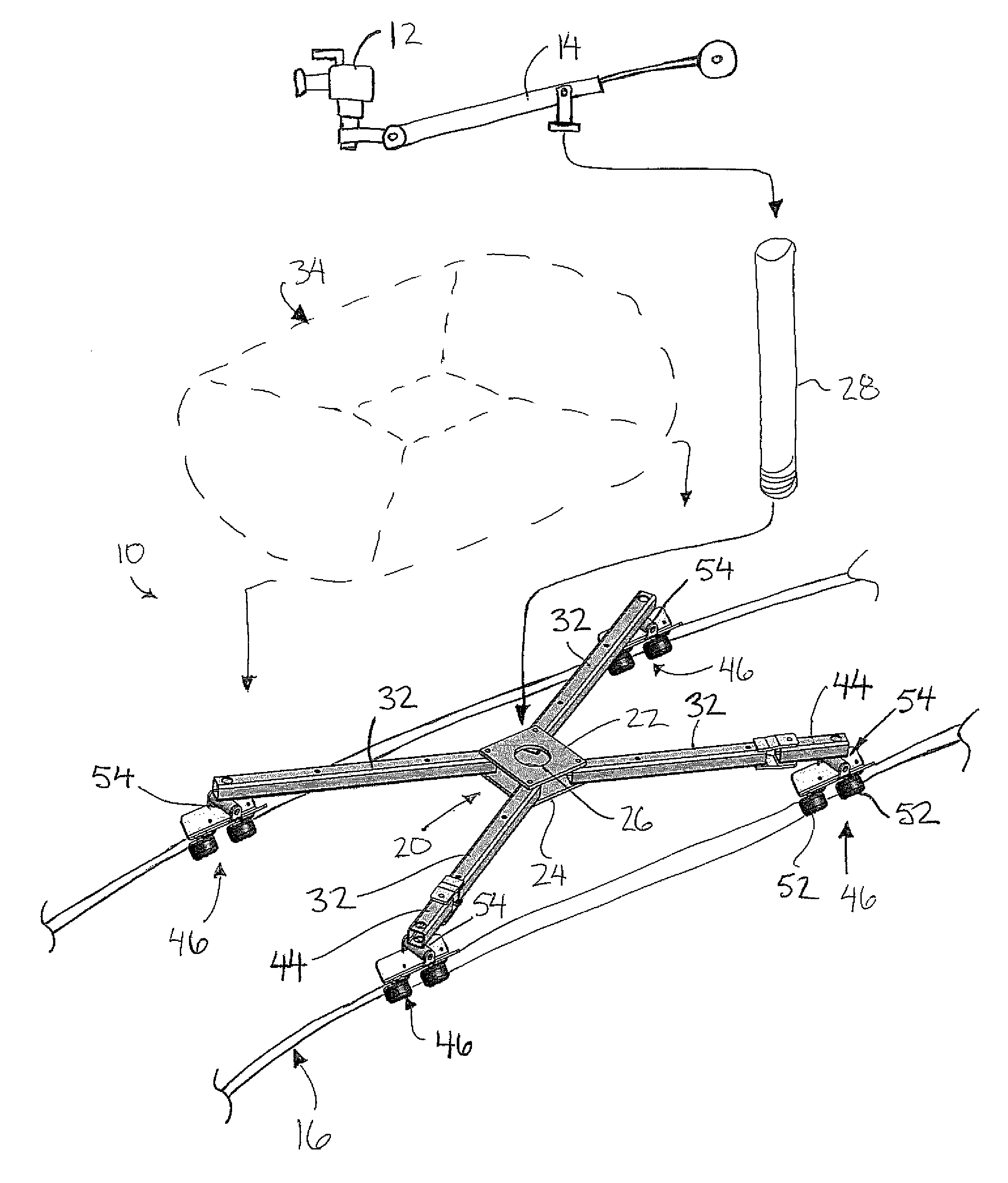
[0048]Referring to the accompanying figures there is illustrated a camera dolly generally indicated by reference numeral 10. The dolly 10 is particularly suited for supporting a camera 12 on a jib 14 such that the camera is supported for rolling movement along a track 16 in a longitudinal direction of the track. The track 16 typically comprises a pair of rail members which are supported generally parallel and spaced apart from one another.

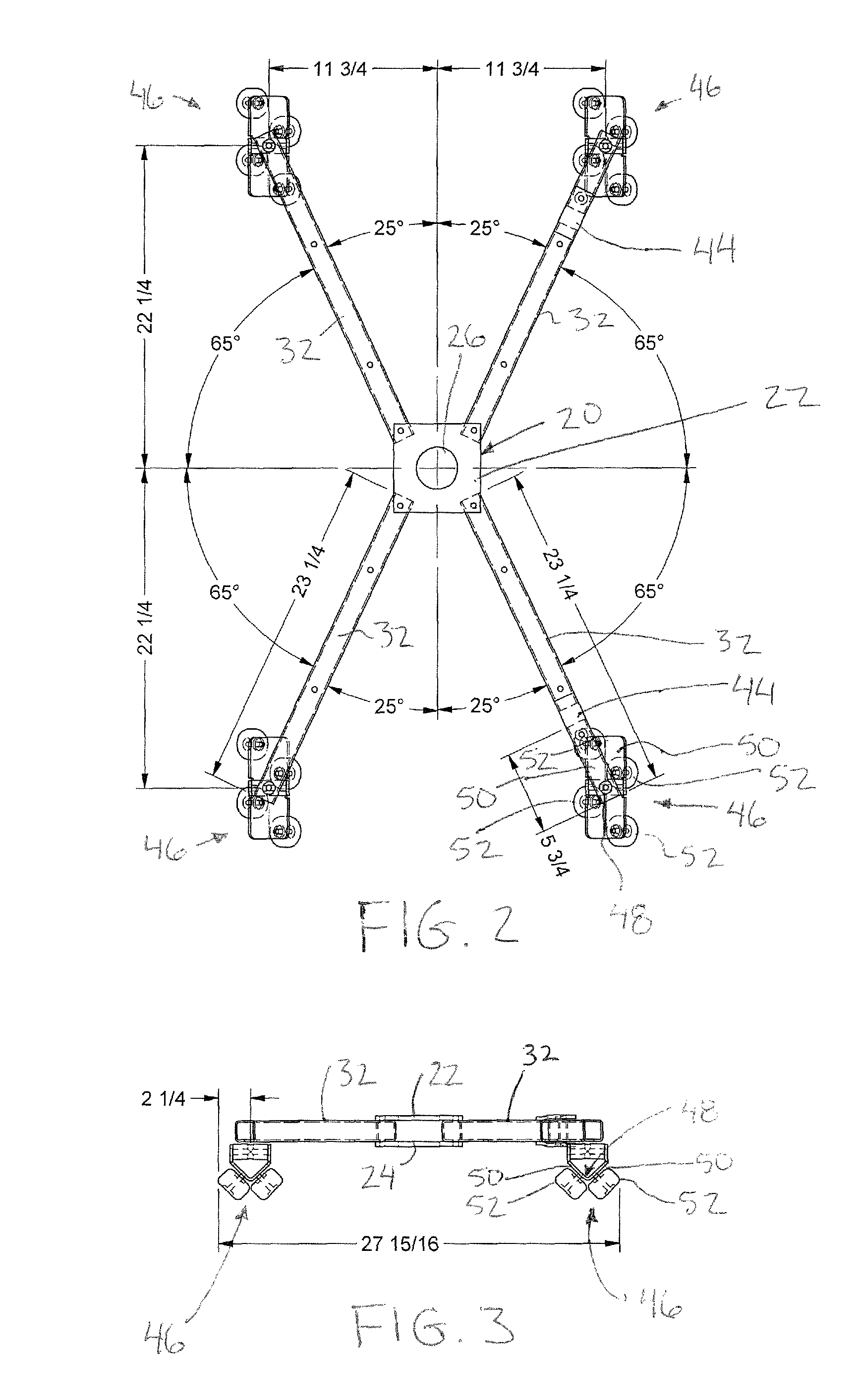
[0049]The dolly 10 includes a base 20 comprising a central member in the form of an upper plate 22 and a lower plate 24, each arranged to span horizontally spaced apart one directly above the other. Each of the plates is generally square in shape and oriented with the corners aligned with one another. A central aperture 26 is provided in the plates which is internally threaded to define a threaded socket which receives the bottom end of an upright mounting post 28 therein. The bottom end of the post includes suitable threads thereon for mating conn...


PUM


Abstract

A camera dolly comprises a base and a plurality of legs extending radially outward from an inner end pivotally coupled on the base to an outer end supporting a wheel assembly thereon such that the wheel assemblies are arranged for rolling movement along a pair of rail members extending in a longitudinal direction. Each wheel assembly comprises a plurality of wheels spaced apart from one another in the longitudinal direction in two rows arranged to receive the respective rail member therebetween. Each wheel assembly is pivotal about an upright axis and a horizontal axis relative to the respective leg. A horizontal deck plate includes plural sets of mounting apertures therein corresponding to different relatively fixed relationships of the legs. A socket formed centrally in the base threadably receives an upright post therein which support the camera thereon spaced above the base.

Description

[0001]This application claims the benefit under 35 U.S.C. 119(e) of U.S. provisional application Ser. No. 61 / 027,218, filed Feb. 8, 2009.FIELD OF THE INVENTION[0002]The present invention relates to a camera dolly for supporting a camera for rolling movement along the ground, and more particularly the present invention relates to a camera dolly including pivotally supported wheel assemblies arranged for rolling along a track.BACKGROUND[0003]Camera dollies are well known for supporting various forms of cameras thereon for rolling movement along a desired path while capturing video with the camera. Many types of camera dollies are particularly suited for following a pair of parallel and spaced apart rails which define a track along which the dolly rolls. The dolly typically includes wheel assemblies which roll along the rails of the track in which the wheel assemblies are known to have a plurality of wheels spaced apart in the direction of rolling movement. The wheel assemblies are typ...

Claims


Application Information

Patent Timeline
Patent Type & Authority Patents(United States)
IPC IPC(8): A47K1/04
CPCB66F11/048F16M11/42F16M11/08F16M11/2021F16M11/425Y10T16/184F16M2200/044F16M2200/068F16M2200/08
Inventor WOOD, DENNIS
Owner WOOD DENNIS
Why Eureka
Try Eureka