Artificial intervertebral joint permitting translational and rotational motion

a technology of intervertebral joints and prostheses, applied in the field of intervertebral joint prosthesis, can solve the problems of increasing the stress on adjacent spinal motion segments, affecting the quality of life of patients, and predisposing neighboring spinal motion segments to rapid deterioration, so as to reduce or eliminate the need for in vivo adjustment, the effect of low profil

Inactive Publication Date: 2012-06-26
WARSAW ORTHOPEDIC INC
View PDF47 Cites 9 Cited by
  • Summary
  • Abstract
  • Description
  • Claims
  • Application Information

AI Technical Summary

Benefits of technology

[0016]The present invention provides an intervertebral joint prosthesis, and tools and methods for implantation, which allows a normal range of translation and rotation between the adjacent vertebrae to which the prosthesis has been fastened. The prosthesis is easy to implant via its flanges, obviating the need for distention of the adjacent vertebrae to widen the disc space. The intervertebral joint prosthesis is also implanted with a predetermined orientation of the prosthesis or spatial relationship between its components, which reduces or eliminates the need for in vivo adjustment. The prosthesis of the present invention also has a low profile and a minimal number of parts. These and other advantages will be clear to one of ordinary skill in the art by reference to the drawings and to the detailed description herein.

Problems solved by technology

There is increased concern in the spinal medical community, however, that the biomechanical rigidity of the intervertebral fusion may predispose neighboring spinal motion segments to rapid deterioration.
That lack of mobility may increase the stresses on adjacent spinal motion segments.
The latter may lead to excessive stresses on the prosthesis leading to wear or failure or be transferred to adjoining motion segments provoking pain and / or accelerated degeneration.
Further, many prior devices are relatively difficult to implant.
Such an operation presents additional risk of injury to the vertebrae themselves from misplacement or scratching by the anchors, and to other tissues due to the spreading of the vertebrae beyond its normal span.

Method used


Image

  • Artificial intervertebral joint permitting translational and rotational motion
  • Artificial intervertebral joint permitting translational and rotational motion
  • Artificial intervertebral joint permitting translational and rotational motion

Examples


Embodiment Construction

[0037]For the purposes of promoting an understanding of the principles of the invention, reference will now be made to the embodiment illustrated in the drawings and specific language will be used to describe the same. It will nevertheless be understood that no limitation of the scope of the invention is thereby intended, such alterations and further modifications in the illustrated device, and such further applications of the principles of the invention as illustrated therein, being contemplated as would normally occur to one skilled in the art to which the invention relates.

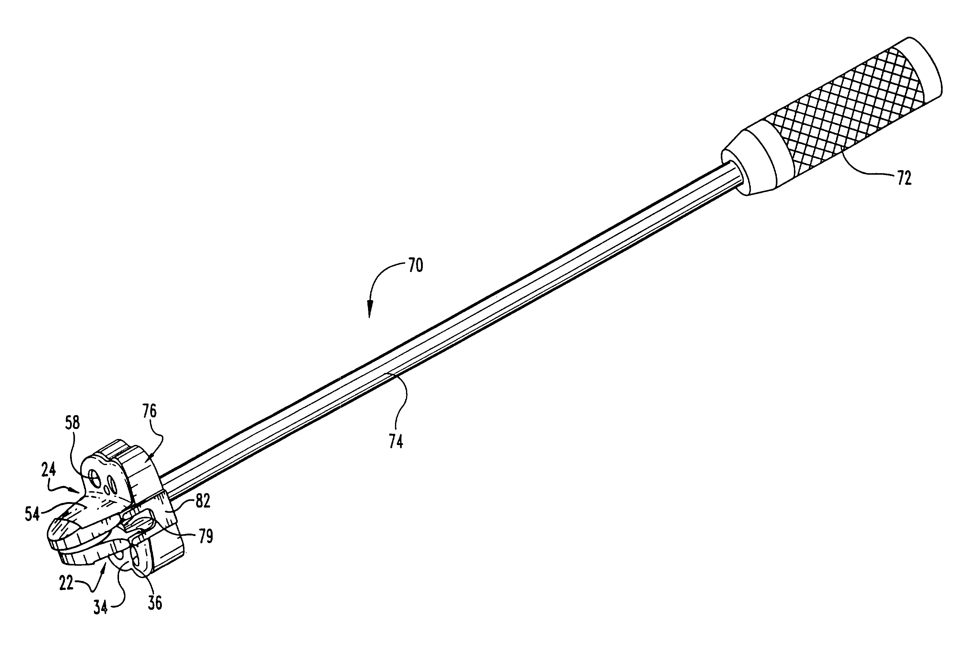
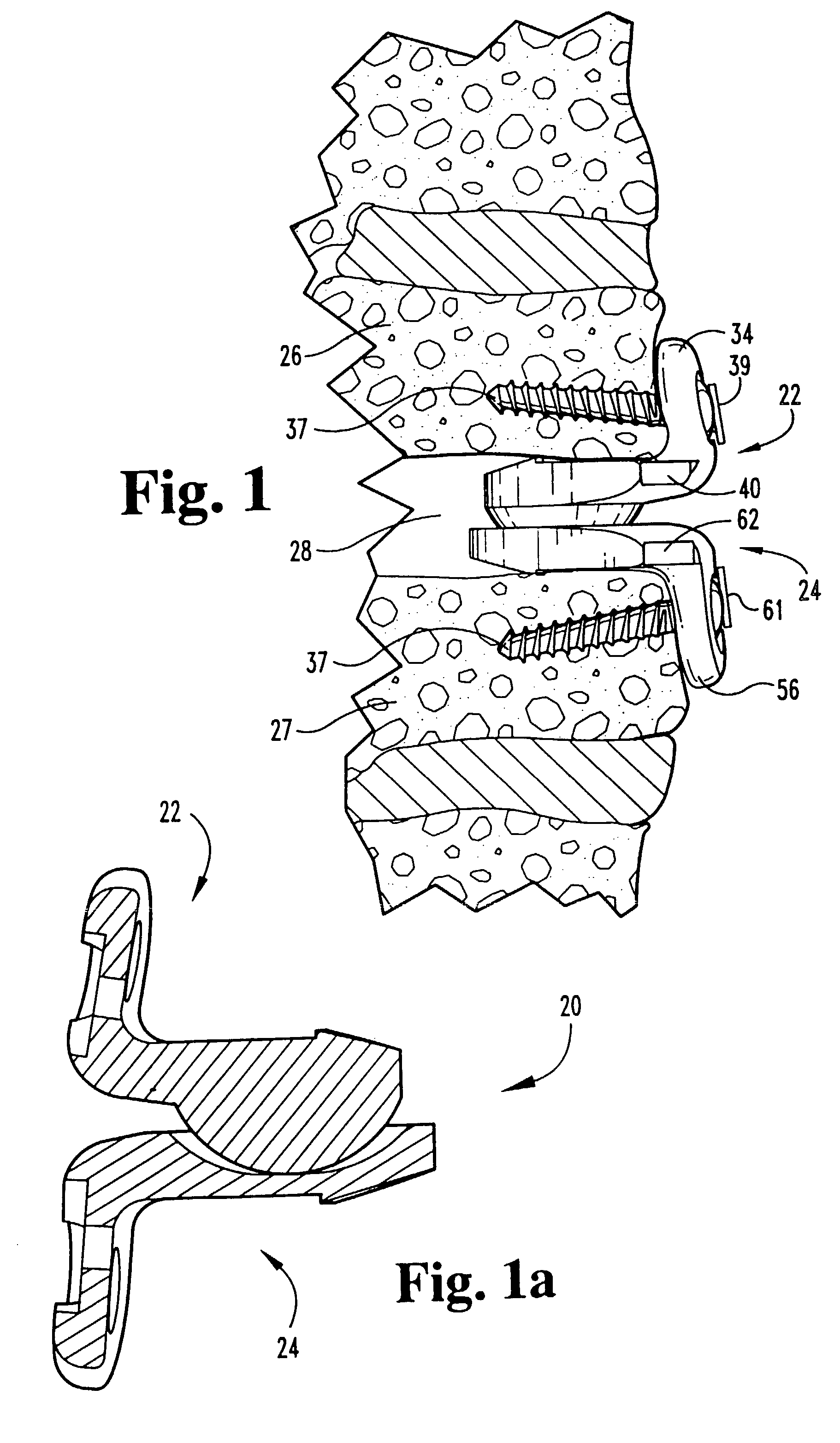
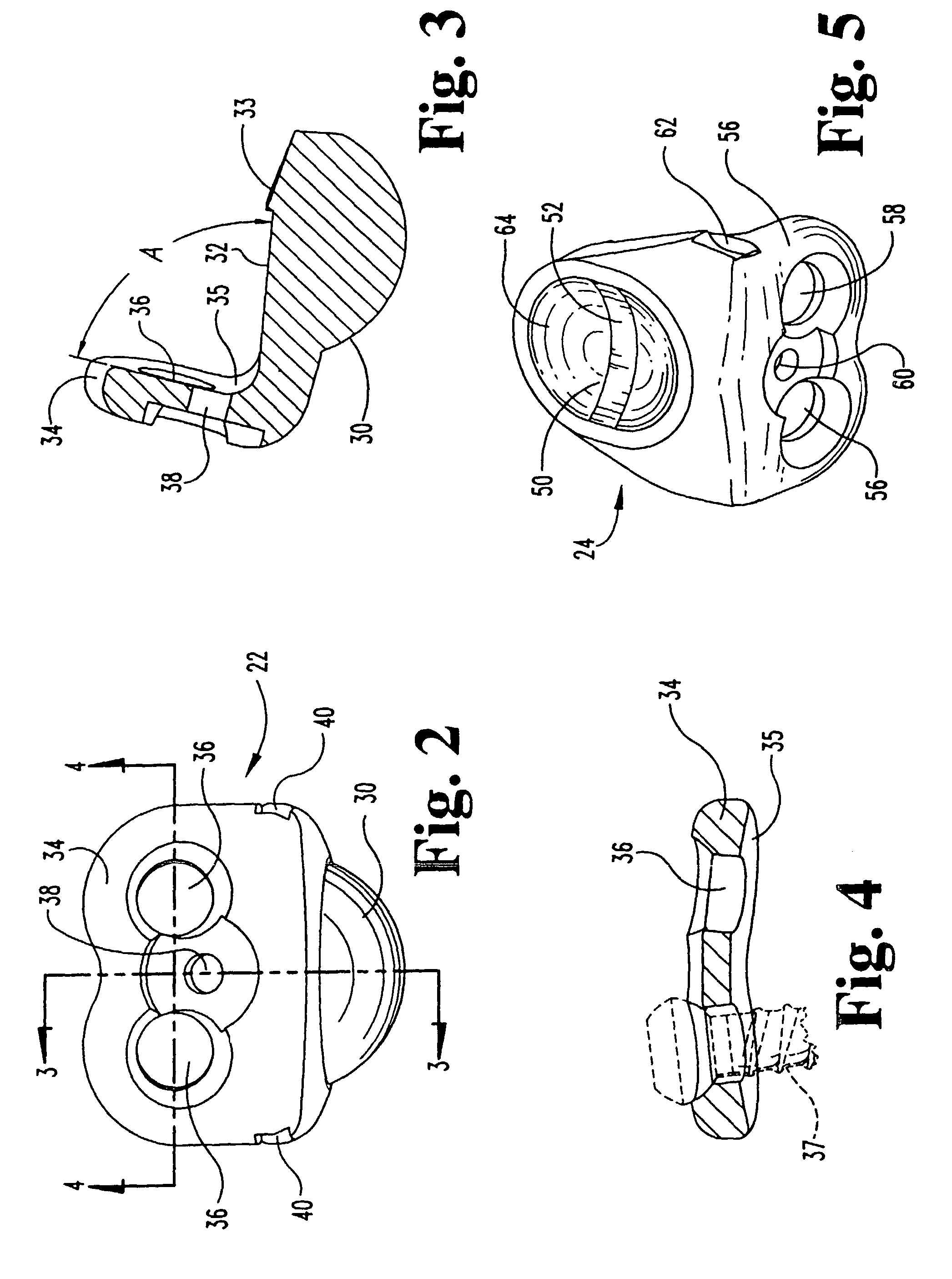
[0038]Referring generally to FIGS. 1-12, there is shown one embodiment of the intervertebral joint prosthesis 20 of the present invention. Prosthesis 20 includes a ball component 22 and a trough component 24 that are interengagable to form prosthesis 20. In an intervertebral disc space 28 between two adjacent vertebrae 26, 27, ball component 22 is fixed to one of the adjacent vertebrae (e.g. vertebra 26 in FIG....


PUM


Abstract

An intervertebral joint prosthesis having a ball component (22) for engagement with a first vertebra (26) and a trough component (24) for engagement with a second vertebra (27) adjacent to the first vertebra is disclosed. The trough component (24) includes a generally concave surface (50) having a substantially flat portion (52). When the ball component (22) and the trough component (24) are engaged to their respective vertebrae, the ball component (72) and the trough component (24) engage each other, permitting rotation and translation of the vertebrae with respect to each other. Both components include a flange (34,56) for engaging a vertebra. The invention also contemplates a method for and a tool for use in implanting a two-piece intervertebral joint prosthesis.

Description

[0001]This application is a continuation of U.S. patent application Ser. No. 09 / 534,767 entitled ARTIFICIAL INTERVERTEBRAL JOINT PERMITTING TRANSLATIONAL AND ROTATIONAL MOTION, filed Mar. 24, 2000 by the same inventors now U.S. Pat. No. 6,540,785, which is a division of U.S. patent application Ser. No. 09 / 177,317 having the same title, filed Oct. 22, 1998 (now U.S. Pat. No. 6,113,637).FIELD OF THE INVENTION[0002]The present invention is directed to an intervertebral joint prosthesis. Specifically, the invention includes a device which is implanted in place of degenerated or absent intervertebral disc tissue, and tools and methods for implanting the same.BACKGROUND OF THE INVENTION[0003]In the treatment of diseases, injuries or malformations affecting spinal motion segments (which include two adjacent vertebrae and the disc tissue or disc space between them), and especially those affecting disc tissue, it has long been known to remove some or all of a degenerated, ruptured or otherwi...

Claims


Application Information

Patent Timeline
Patent Type & Authority Patents(United States)
IPC IPC(8): A61B17/70A61F2/44A61B17/86A61F2/00A61F2/30A61F2/46
CPCA61F2/4425A61F2/4611A61B17/86A61F2002/30369A61F2002/30578A61F2002/30649A61F2002/30654A61F2002/30787A61F2002/30794A61F2002/30828A61F2220/0033A61F2002/3079
Inventor GILL, STEVEN S.WALKER, COLINVAN HOECK, JAMESGAUSE, LARRY
Owner WARSAW ORTHOPEDIC INC
Why Eureka
Try Eureka