Fiber optic connector panel

a fiber optic connector and connector panel technology, applied in the field of fiber optic connector panels, can solve the problems of limited enclosure space, difficult termination and management of fiber cabling, and fiber-based applications,

Active Publication Date: 2012-06-26
ADTRAN
View PDF20 Cites 8 Cited by
  • Summary
  • Abstract
  • Description
  • Claims
  • Application Information

AI Technical Summary

Benefits of technology

[0010]In another aspect, the first and second cylindrically configured cable storage members are the same size. The fiber optic connector comprises an “n” position bulkhead fitting in another example. The fiber optic connector and the splice storage member are supported at opposing sides to each other and both

Problems solved by technology

Fiber-based applications, i.e., PON (passive optical network), on the other hand, have limited available space in the enclosure.
This makes it difficult to terminate and manage the fiber cabling, which must be extended from the channel bank to the OSP environment, and eventually to the c

Method used


Image

  • Fiber optic connector panel
  • Fiber optic connector panel
  • Fiber optic connector panel

Examples


Embodiment Construction

[0016]Different embodiments will now be described more fully hereinafter with reference to the accompanying drawings, in which preferred embodiments are shown. Many different forms can be set forth and described embodiments should not be construed as limited to the embodiments set forth herein. Rather, these embodiments are provided so that this disclosure will be thorough and complete, and will fully convey the scope to those skilled in the art. Like numbers refer to like elements throughout.

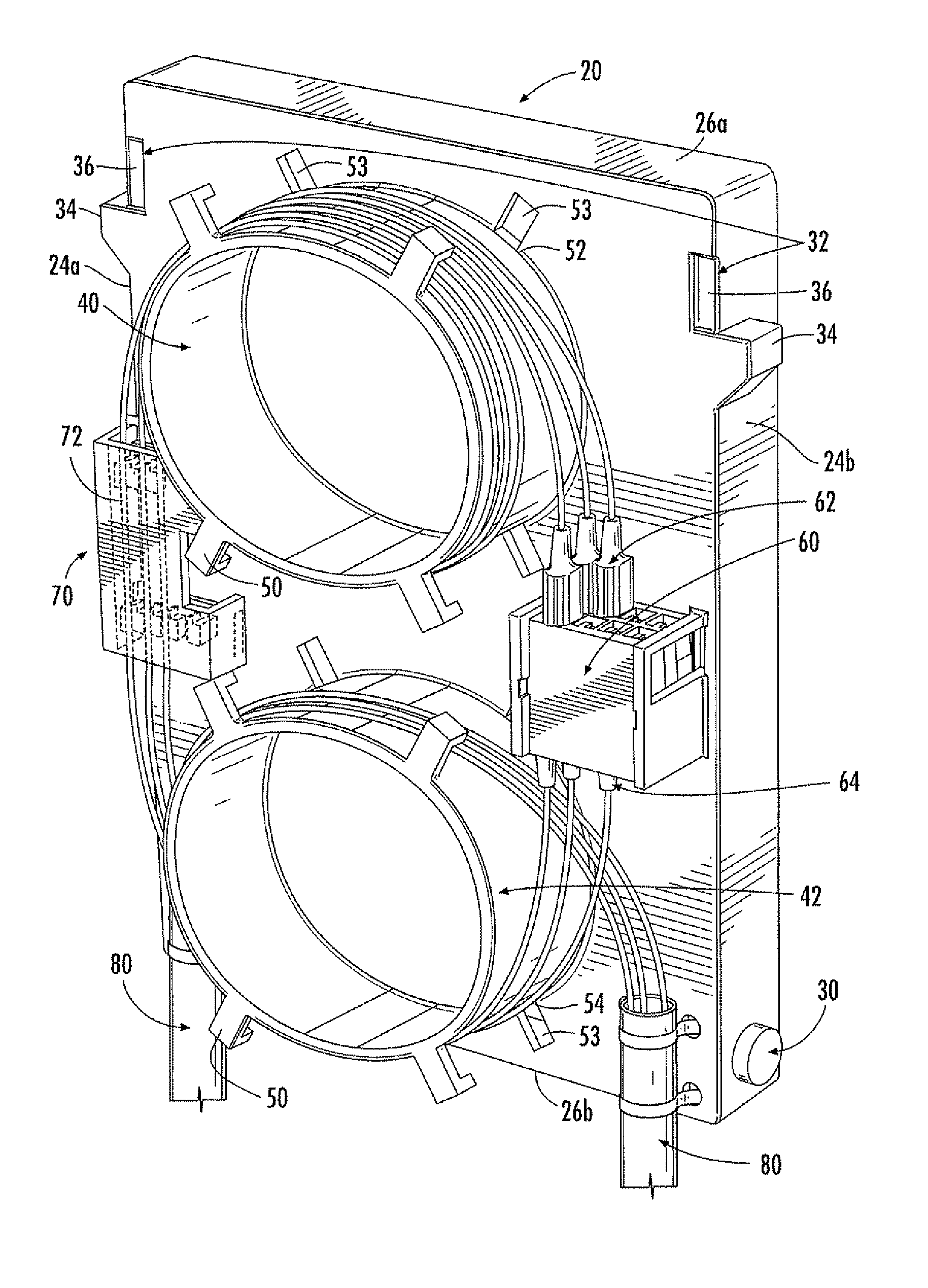
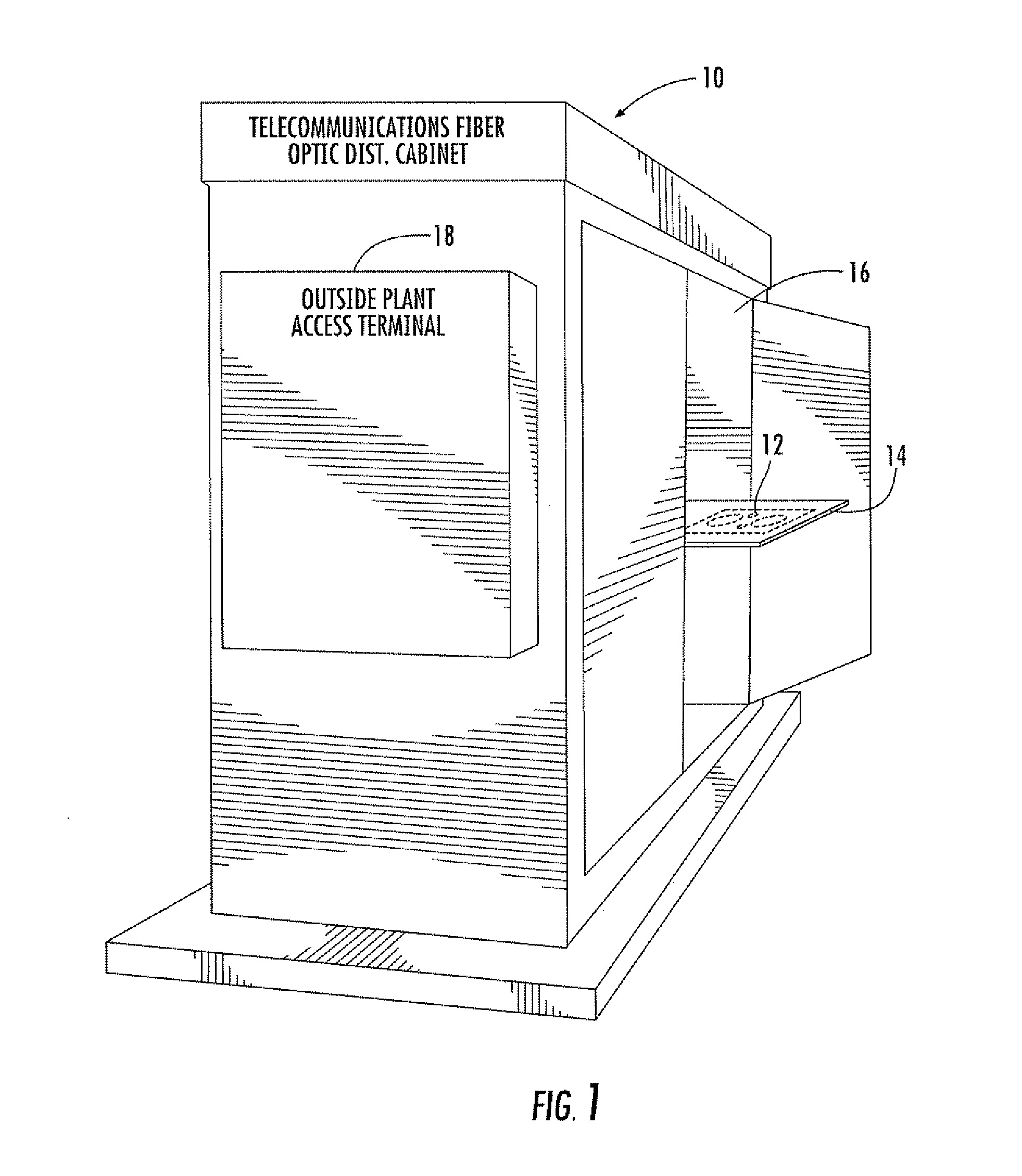
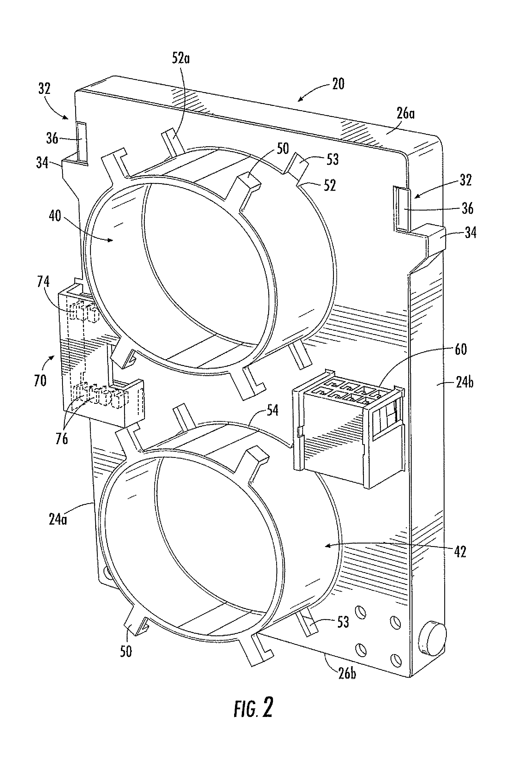
[0017]The fiber optic connector panel, in accordance with a non-limiting aspect, takes the place of a legacy copper terminating 307 block and mounts into the same apparatus or support, i.e., in this disclosure referred to as the telecommunications fiber optic distribution cabinet, as used currently for the 307 lightning protection block. The installation of the panel is “snap in,” which makes the fiber transition relatively simple for an installer. The 307-type connector block typically provide...


PUM


Abstract

A fiber optic connector panel fits within a telecommunications fiber optic distribution cabinet and terminates and protects outside plant cables. A support panel is pivotally mounted into a telecommunications fiber optic distribution cabinet. A first cylindrically configured cable storage member is supported by the support panel and configured to store any slack fiber optic pigtails. A second cable storage member is supported by the support panel and configured to store any slack outside plant cable and jumpers. A fiber optic connector is supported by the support panel and configured to connect fiber optic pigtails and fiber optic jumpers. A splice storage member is supported by the support panel and configured to store fiber optic cable splices of the fiber optic pigtails and outside plant cable and jumpers of the fiber optic pigtails and outside plant cable and jumpers.

Description

FIELD OF THE INVENTION[0001]This invention relates to fiber optic connector panels, and more particularly, this invention relates to fiber optic connector panels that terminate and protect outside plant cables.BACKGROUND OF THE INVENTION[0002]Legacy and current Broadband Digital Loop Carrier (BDLC) Outside Plant (OSP) enclosures are designed primarily for termination and distribution of copper-based subscriber circuits. The cabinets are typically designed with minimal space for other equipment (passive or active) in the system. Fiber-based applications, i.e., PON (passive optical network), on the other hand, have limited available space in the enclosure. This makes it difficult to terminate and manage the fiber cabling, which must be extended from the channel bank to the OSP environment, and eventually to the customer. Historically, this termination and management have been performed in a rack-mounted fiber termination panel, which includes:[0003]1) A set of bulkhead panels to which...

Claims


Application Information

Patent Timeline
IPC IPC(8): G02B6/00
CPCG02B6/4455
Inventor MORGAN, JOSHUACRAWFORD, JASON
Owner ADTRAN
Why Eureka
Try Eureka