Mounting support for photovoltaic modules

a photovoltaic module and mounting support technology, applied in the direction of heat collector mounting/support, solar heating energy, walls, etc., can solve the problems of low energy efficiency of the modular foil, high material cost, etc., and achieve the effect of not easy to roll up

Active Publication Date: 2012-07-03
ADENSIS
View PDF23 Cites 23 Cited by
  • Summary
  • Abstract
  • Description
  • Claims
  • Application Information

AI Technical Summary

Benefits of technology

[0008]This type of support advantageously allows mounting of photovoltaic modules based on glass technology without a heavy substructure. The support according to the invention (here also referred to as flexible tape, mounting foil, web) can be readily transported when rolled up, and can be easily handled during installation. The mounting support is already well prepared for the installation because the fastening members are preinstalled. The proposed mounting device is not limited to flat roofs.
[0010]According to another advantageous feature of the present invention, the top side of the strip may include recesses oriented perpendicular to the longitudinal direction of the strip, with the recesses separating corresponding strip segments, and the fastening members may be arranged in a part of the strip segments. With this approach, elongated mounting supports can be provided which may prevent the material from protruding over the edges of the rolled-up support. In addition, rainwater entering between the photovoltaic modules can be easily diverted to the sides.
[0012]According to another advantageous feature of the present invention, the top side of the strip may include grooves oriented in the longitudinal direction of the strip and forming ribs therebetween, wherein the fastening members are arranged in at least part of the ribs. In this way, the repeat pattern can advantageously be freely selected, because there a no longer defined transverse grooves in form of recesses.
[0013]According to another advantageous feature of the present invention, the top side of the strip may include a plurality of small tubes, with the fastening members, e.g., a threaded element, being arranged in at least one of the tubes. Such tube system, which preferably has a honeycomb structure, allows the mounting support to be easily rolled up, while still allowing a flexible installation.
[0014]It should be mentioned that the fastening members should protrude only slightly over the top side of the mounting support, so that the mounting support can be uniformly rolled up into a roll. A maximum overhang of half the thickness of the support can already be considered as a limit. Advantageously, the overhang does not to exceed 30%, preferably 15%, of the thickness of the support. Most preferably, the fastening members is completely integrated in the support so as not to hinder the support from being rolled up or unrolled.
[0018]Depending on the mounting method on the roof layer and the fastening members, the lateral edges of the mounting support may advantageously also include a recess, which could be used, for example, to precisely guide a welding apparatus. In a two-layer structure, the bottom layer would then be continuous without recesses, whereas the top layer would have island-shaped raised portions representing the segments. Such embodiment would be of interest because of low material consumption and a small weight.

Problems solved by technology

In addition, the material costs are also very high.
A drawback of the support structure described in DE 20 2006 016 382 U1 is the use of modular photovoltaic foils which are connected with a mounting foil glued to the roof surface of the flat roof because of a low energy efficiency of the modular foil.

Method used


Image

  • Mounting support for photovoltaic modules
  • Mounting support for photovoltaic modules
  • Mounting support for photovoltaic modules

Examples


Embodiment Construction

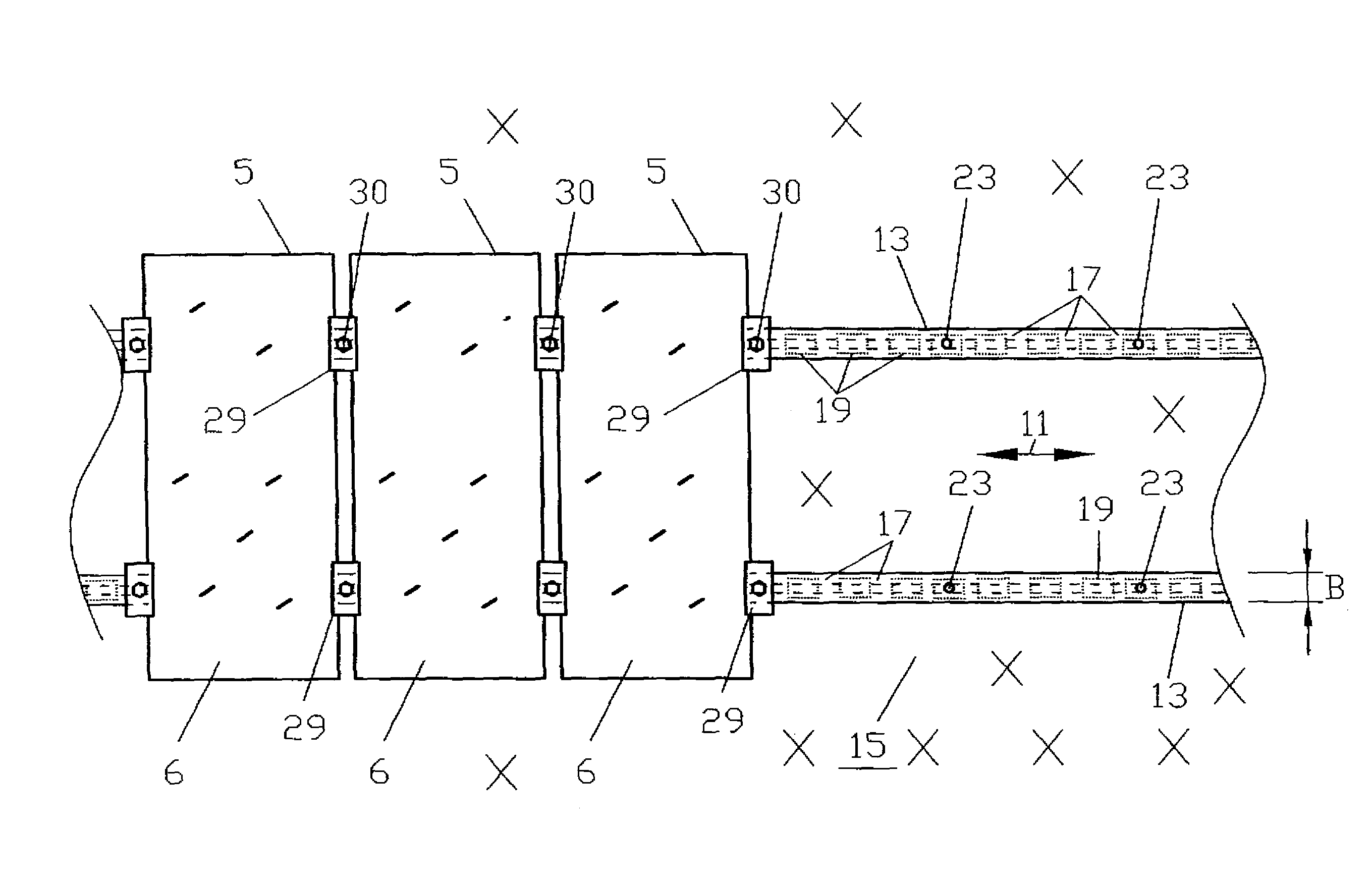
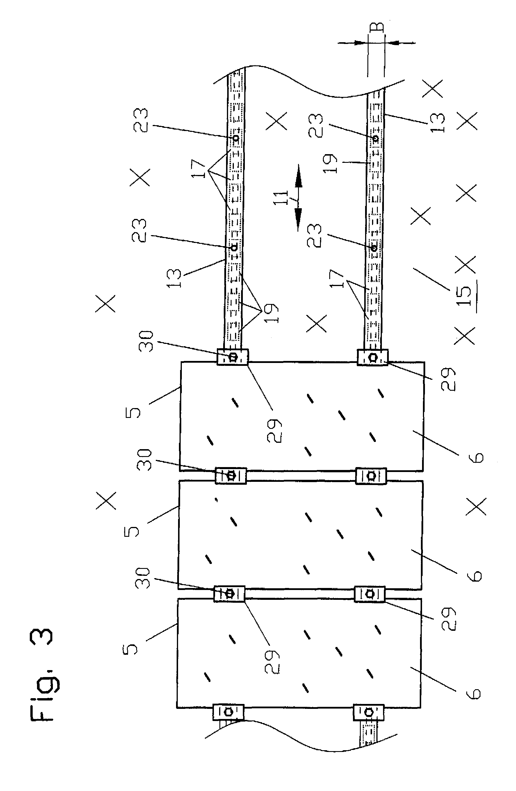
[0033]Throughout all the figures, same or corresponding elements may generally be indicated by same reference numerals. These depicted embodiments are to be understood as illustrative of the invention and not as limiting in any way. It should also be understood that the figures are not necessarily to scale and that the embodiments are sometimes illustrated by graphic symbols, phantom lines, diagrammatic representations and fragmentary views. In certain instances, details which are not necessary for an understanding of the present invention or which render other details difficult to perceive may have been omitted.

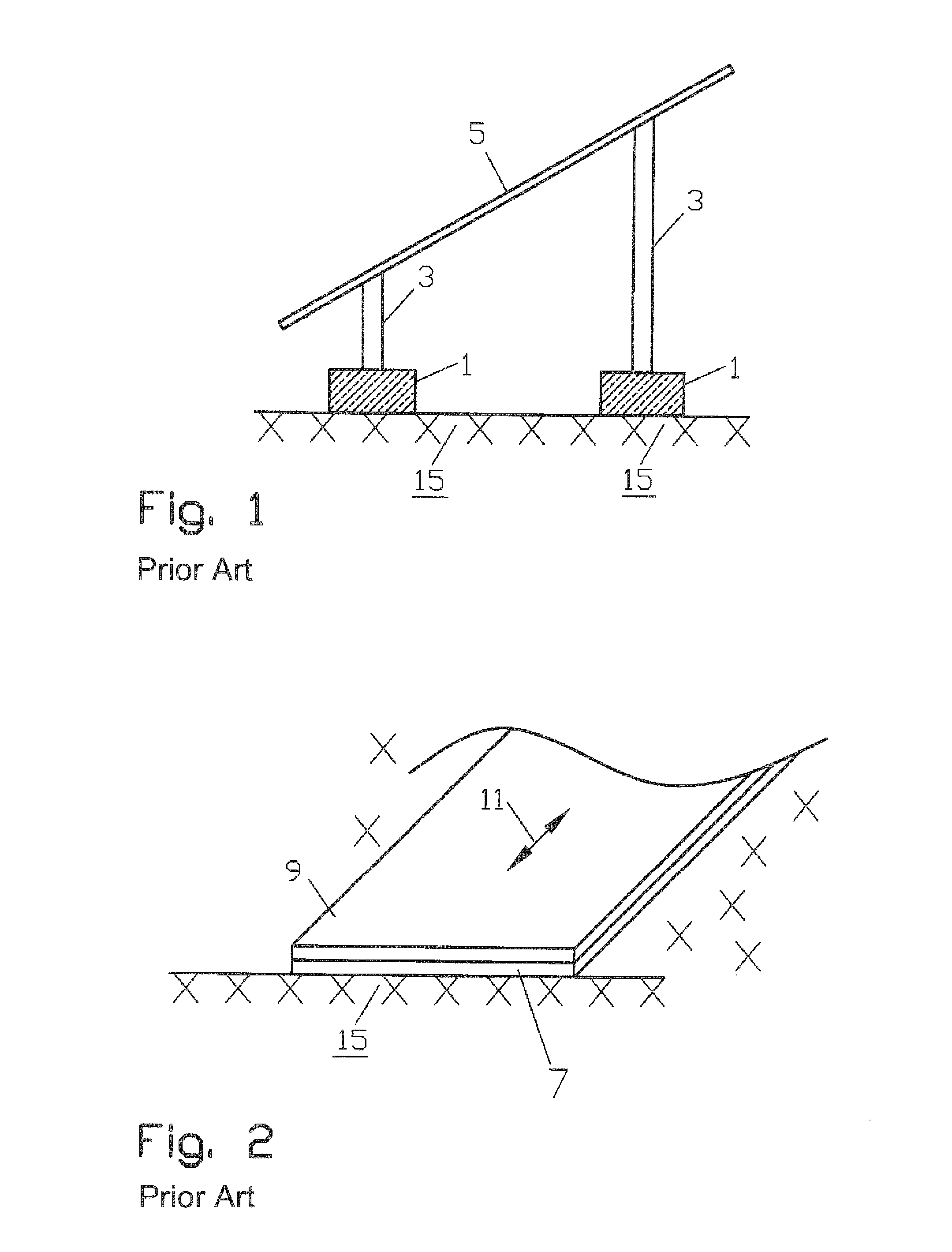
[0034]Turning now to the drawing, and in particular to FIGS. 1 and 2, there are shown two conventional methods for securing a solar collector facility to a flat roof. FIG. 1 shows a conventional installation of photovoltaic modules, wherein concrete blocks 1 placed on a water-tight and air-tight roof surface 15 of a roof. Connected thereto is a support structure 3, on which ...


PUM

PropertyMeasurementUnit
widthaaaaaaaaaa
widthaaaaaaaaaa
lengthaaaaaaaaaa

Abstract

A mounting support for mounting photovoltaic modules constructed with at least one glass pane on a flat roof surface includes a flexible elongated strip having a bottom side with a substantially smooth surface for attachment to the roof surface and a top side with a substantially smooth surface for supporting the photovoltaic modules. The top side of the strip includes recesses oriented perpendicular to the longitudinal direction of the strip and separating strip segments which allows the mounting support or strip to be easily rolled up. The strip segments include integrally formed fastening members configured to engage with cooperating fasteners for securing the photovoltaic modules on top side of the strip. The top surface may also include longitudinal grooves or tubes holding the fastening members.

Description

CROSS-REFERENCES TO RELATED APPLICATIONS[0001]This application claims the priority of German Patent Application, Serial No. 10 2007 056 619.2, filed Nov. 23, 2007, pursuant to 35 U.S.C. 119(a)-(d), the content of which is incorporated herein by reference in its entirety as if fully set forth herein.BACKGROUND OF THE INVENTION[0002]The present invention relates to a photovoltaic module, and more particularly to a support for installing a photovoltaic module on a roof.[0003]Nothing in the following discussion of the state of the art is to be construed as an admission of prior art.[0004]Solar energy collectors can be installed on a flat roof by arranging photovoltaic or solar modules constructed with glass panels in side-by-side relationship. These modules are planar panel-like assemblies in form of rectangular or square panels. The panels are typically supported on the roof surface (e.g., tarpaper, tiles, plastic foil) by concrete blocks placed on the flat roof, with a corresponding s...

Claims


Application Information

Patent Timeline
Patent Type & Authority Patents(United States)
IPC IPC(8): E04H12/18E04H14/00E04D1/00A47G29/02A47F5/00H01L31/042F24J2/46B32B3/28F24J2/36
CPCF24J2/5205F24J2/523F24J2/5258H01L31/048H02S20/00F24J2002/4676Y10T428/2457Y02B10/20Y02E10/47Y02E10/50Y10S428/906Y02B10/12F24S25/10F24S25/33F24S25/636F24S2025/601H02S20/24Y02B10/10
Inventor BECK, BERNHARD
Owner ADENSIS
Why Eureka
Try Eureka