Connector system for securing an end portion of a steel structural member to a vertical cast concrete member

a technology of connecting system and steel structural member, which is applied in the direction of manufacturing tools, building scaffolds, mechanical equipment, etc., can solve the problems of putting the worker in an unsafe situation, requiring additional time and expense, etc., and achieves the effect of reducing the time and cost of making, and simplifying the inspection and/or testing of the connection

Active Publication Date: 2012-07-03
CONNECT EZ
View PDF15 Cites 16 Cited by
  • Summary
  • Abstract
  • Description
  • Claims
  • Application Information

AI Technical Summary

Benefits of technology

[0004]In the illustrated embodiment, the front opening within the receiver and the vertical plate of the support bracket are generally triangular, and the horizontal plate of the support bracket has notches or recesses adjacent the vertical plate for receiving the front wall portions of the receiver. The connector system provides a number of advantages such as eliminating field welding during erection, avoiding the need for a worker to climb a ladder or use a hydraulic lift to a position adjacent the connector system, significantly reduces the time and cost for making a connection, provides a safe means for making a connection and simplifies the inspection and / or testing of the connection at the elevated site during erection.

Problems solved by technology

This requires the worker to climb a ladder extending to the wall connector or to a scaffold adjacent the wall or use a hydraulic lift, all of which requires additional time and expense for connecting a beam or joist to a wall and sometimes places the worker in an unsafe situation.

Method used


Image

  • Connector system for securing an end portion of a steel structural member to a vertical cast concrete member
  • Connector system for securing an end portion of a steel structural member to a vertical cast concrete member
  • Connector system for securing an end portion of a steel structural member to a vertical cast concrete member

Examples


Embodiment Construction

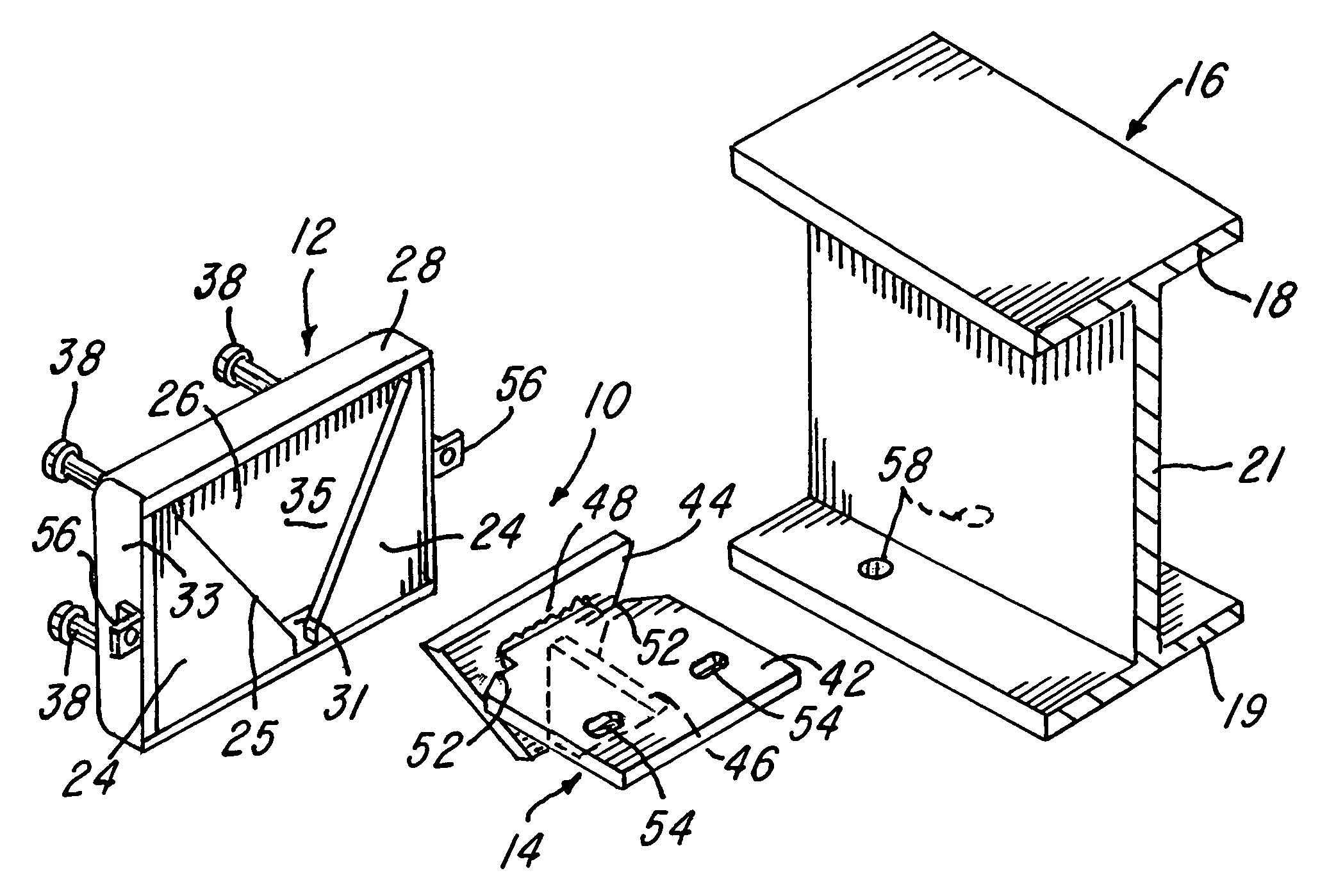
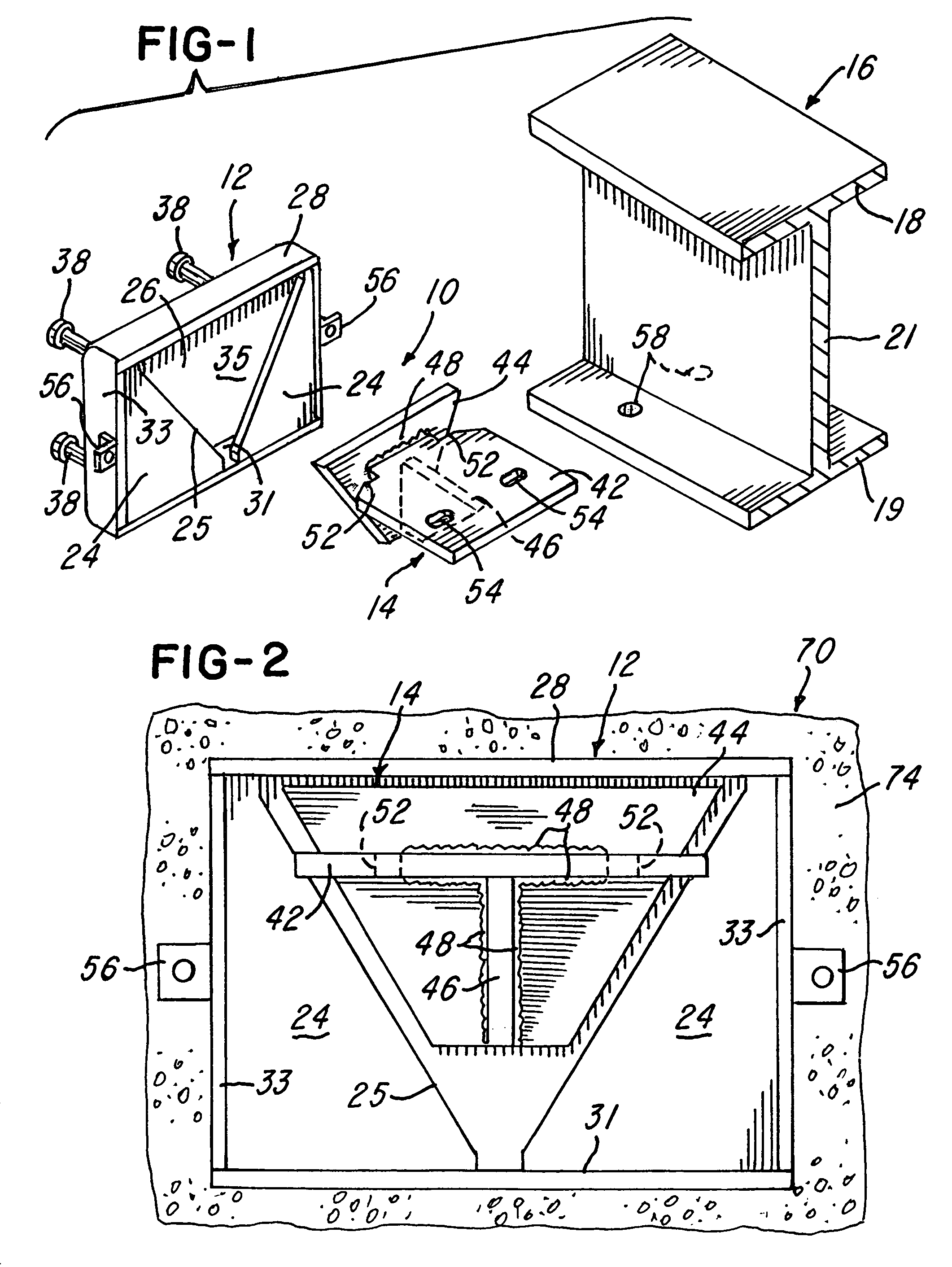
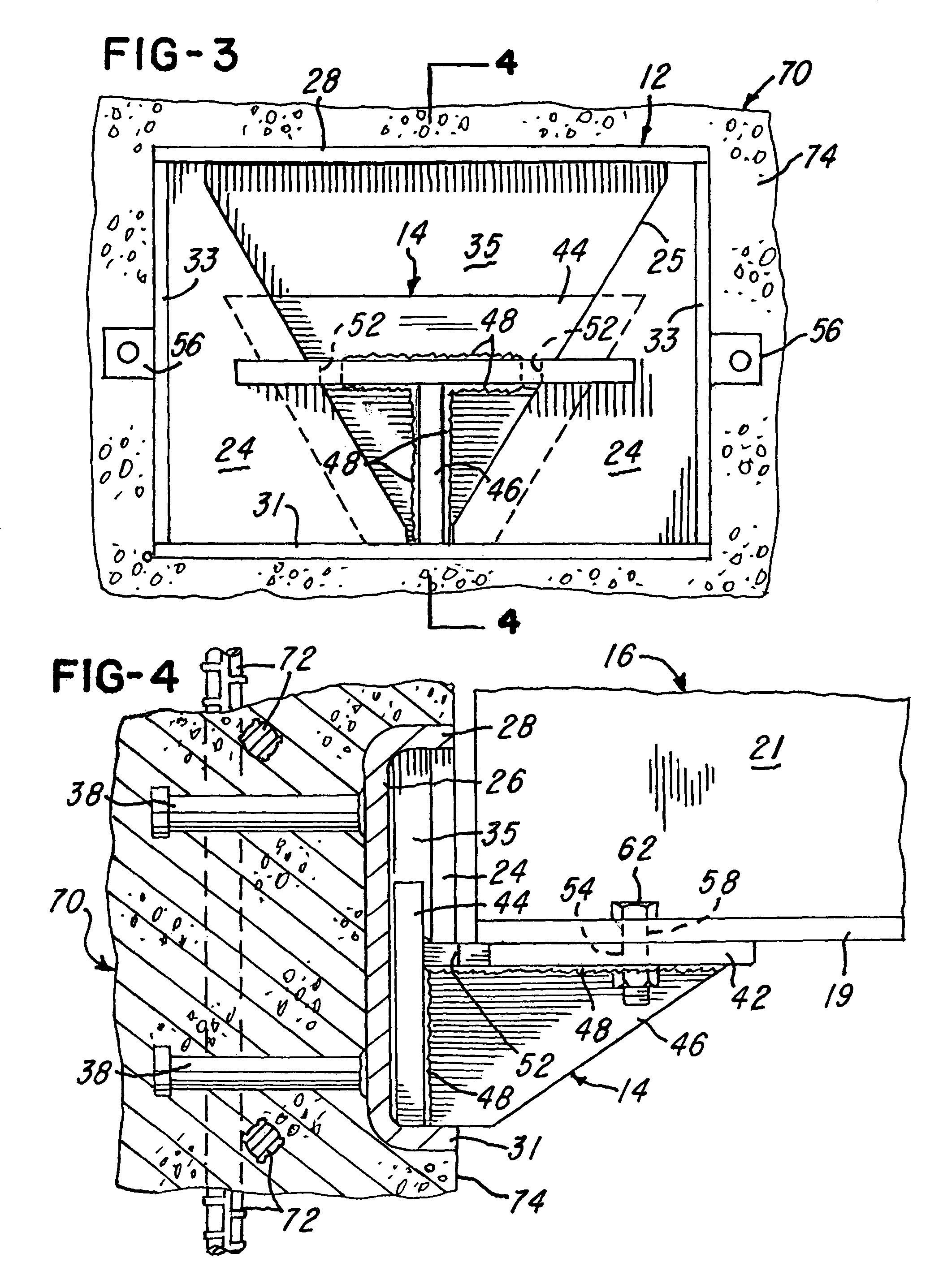
[0010]Referring to FIG. 1, a connector system 10 constructed in accordance with the invention includes a fabricated metal or steel receiver 12 and a T-shape support bracket 14. The bracket 14 is adapted to receive and support an end portion of an elongated structural steel member illustrated in the form of a steel H-beam 16. However, the structural steel member may also be a steel truss joist or any other member used to construct a building or similar structure. As shown, the H-beam 16 has an upper flange portion 18 and a lower flange portion 19 integrally connected by a vertical web portion 21. As used herein, it is to be understood that the term beam includes a steel truss joist or any other structural member.

[0011]The fabricated steel receiver 12 is illustrated in the form of a box and includes opposing flat front wall portions 24 which defines a generally triangular opening 25 and is rigidly connected to a flat rear wall portion 26 by a top wall portion 28, a bottom wall portion...


PUM


Abstract

A steel structural member such as a joist or beam is secured to a vertical cast concrete member or wall by a connector system including a fabricated steel receiver embedded within the wall. Embedded anchors are attached to the receiver which has front wall portions flush with the concrete wall and define a front opening. A support bracket has a horizontal plate attached to the beam and a vertical plate which fits through the front opening within the receiver. The bracket is attached to the beam which is then elevated, and the vertical plate is inserted through the opening into the receiver. The beam and vertical plate are then shifted until opposite edge portions of the vertical plate are blocked by the front wall portions of the receiver. In the illustrated embodiment, the front opening and vertical plate are generally triangular, and the support bracket has a welded reinforcing gusset.

Description

BACKGROUND OF THE INVENTION[0001]In the construction of a building or other structure, it is common to construct cast reinforced concrete walls by using tilt-up precast wall panels or panels precast at a remote plant or by casting concrete walls in place. After the vertical concrete walls are formed, it is common to connect structural steel members such as steel beams or steel truss joists to the concrete walls. Usually steel angle brackets are attached to the walls, for example, as disclosed in U.S. Pat. No. 5,881,519, No. 6,298,630 and No. 6,739,099. Other forms of embedded connectors are disclosed, for example, in U.S. Pat. No. 4,951,438, No. 5,548,939 and No. 6,494,639. In the '639 Patent, a vertical plate is secured to a concrete wall surface by headed concrete anchors and defines keyhole slots for receiving headed studs or pins which project from an angle bracket.[0002]The angle bracket is used to support an end portion of a beam and is also used to attach a wall panel to a co...

Claims


Application Information

Patent Timeline
Patent Type & Authority Patents(United States)
IPC IPC(8): E04B1/34E04B1/38E04B5/00E04B7/00
CPCE04B1/2403E04B1/4114Y10T403/73E04B2001/2415E04B2001/2409F16B2200/67
Inventor FOLEY, ROBERT P.
Owner CONNECT EZ
Why Eureka
Try Eureka