
Modular connector for electric connections

a technology of electric connection and module connector, which is applied in the direction of electrical apparatus, connection, coupling device connection, etc., can solve the problems of lack of protection of current elements, a hindrance to cable handling, and no possibility of identifying conductors

Inactive Publication Date: 2012-07-03
DAISEL INNOVA SL
View PDF10 Cites 1 Cited by
  • Summary
  • Abstract
  • Description
  • Claims
  • Application Information

AI Technical Summary

Benefits of technology

[0007]The modular connectors for electric connections of the present invention have an external anchoring system which facilitates the grouping of components, through tongue and groove couplings which allow convenient constructions for each application.

Problems solved by technology

a) Signalization: There exist no possibility of signaling circuits as there is no cover or possible coupling of the identification element, unless plastic marking washers or labels fixed or tied to the conductor cables are used. The washers have several inconveniences among which we can mention: a) the washers are needed for each set of numbers and / or letters needed for each cable: and b) these washers are not normally attached to the cable so they slide, turn or are lost when it is disconnected. On the other hand, the labels are a hindrance to the handling of cables.
b) Identification: There is no possibility of identifying the conductors by the connector colors as they are colorless elements.
c) Insulation: Some of the current elements lack enough protection as they do not have stops or enough insulation.
d) Cable fastening: Base for fixing the cables with a curved shape, decreasing, with respect to a flat shape, the degree of cable fastening since they are pressed by the screws on the base.
e) Interconnection: Nowadays, terminal blocks are used, which are only sectional without any possibility of interconnecting more elements or different elements.
On the other hand, the terminal blocks of the previous art normally have through holes which enable their fastening by means of screws or riveting to a base, but do not have mechanisms which allow its autonomous grouping without any need of fixing each individual piece to the base but fixing the whole set instead.

Method used


Image

  • Modular connector for electric connections
  • Modular connector for electric connections
  • Modular connector for electric connections

Examples


Embodiment Construction

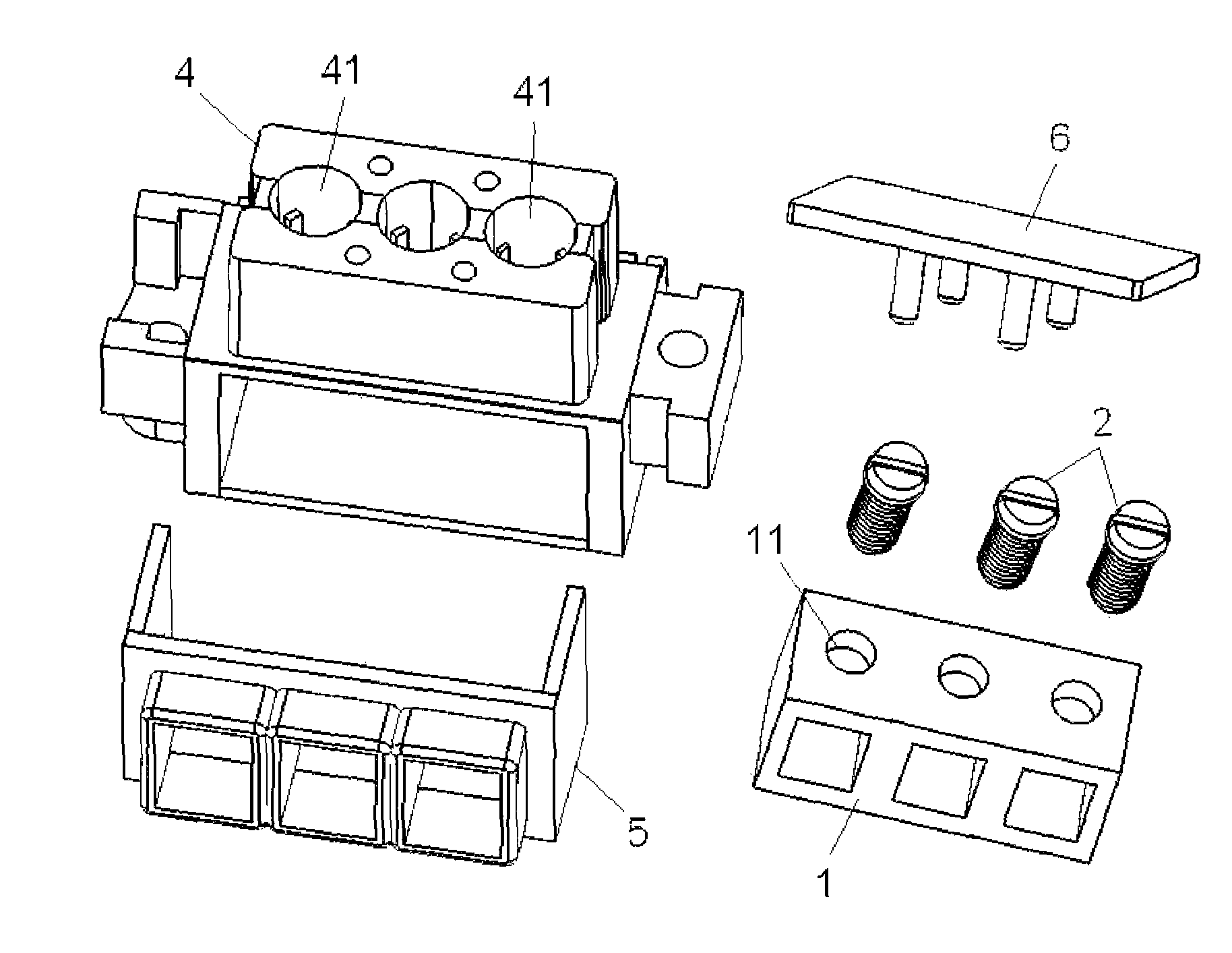
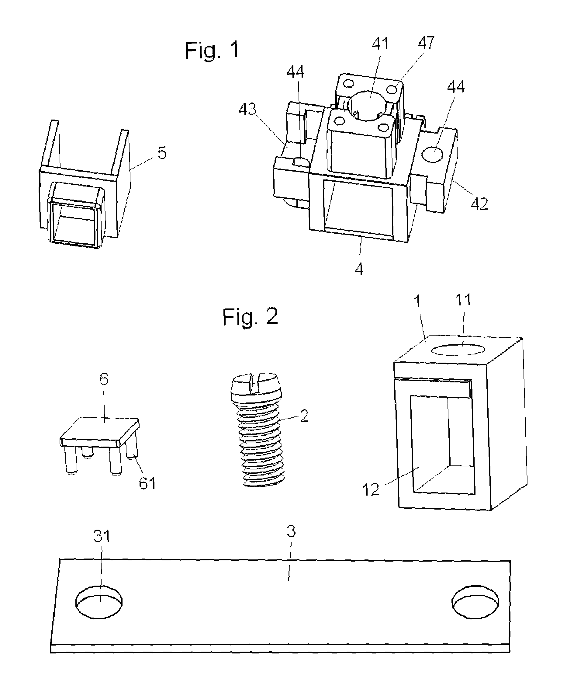
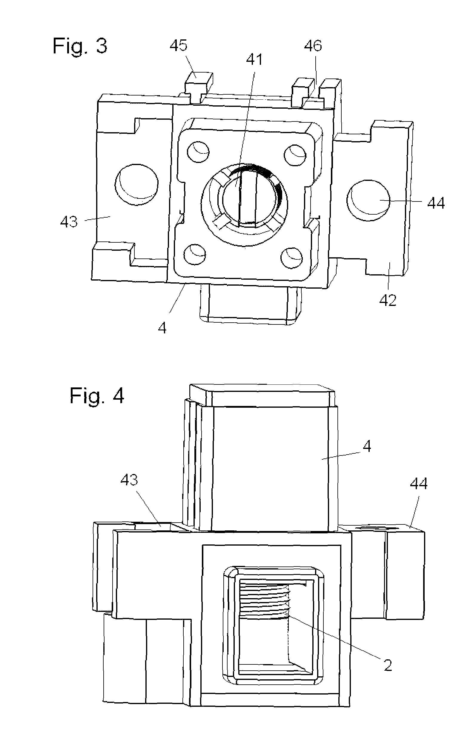
[0007]The modular connectors for electric connections of the present invention have an external anchoring system which facilitates the grouping of components, through tongue and groove couplings which allow convenient constructions for each application.

[0008]For first-sight recognition, the wraparound insulating carcasses are color-keyed to identify the conductors: phase, neutral and safety ground. However, they can be died with the appropriate colors according to the different standards. To that same end, and for a more detailed knowledge of each circuit according to the circuit diagrams, they have an upper thermoplastic cover which can be signaled to the user.

[0009]The conductor part features a set of one or more metallic conductor parts, all of them being of the same pole and the set being enclosed in an insulating thermoplastic wraparound carcass, using the same color of the conductor cable for this element. Each metallic conductor part has a binding screw to fasten the cables h...


PUM


Abstract

Modular connector for electrical connections, provided with an external anchoring system which facilitates the grouping and fixing of several connectors through male and female couplings, both laterally and transversally. For first-sight recognition, the wraparound insulating carcasses (4) are standard color-keyed to identify the conductors. For the recognition of each circuit it is provided with an upper cover (6) which can be signaled by the user. The conductor part has a set of one or more metallic parts always of the same pole (1), and the set is built into a wraparound insulating carcass (5), having the same color as the conductor cable for this element.

Description

[0001]This application is a National Stage Application of PCT / ES2008 / 070145, filed 24 Jul. 2008, which claims benefit of Serial No. P200702312, filed 21 Aug. 2007 in Spain and which application(s) are incorporated herein by reference. To the extent appropriate, a claim of priority is made to each of the above disclosed applications.OBJECT OF THE INVENTION[0002]This invention relates to the connection and identification of electrical conductors and circuits and more particularly to the electric cable connections in facilities for the distribution and control of electric power.BACKGROUND OF THE INVENTION[0003]The existing terminal blocks are often manufactured and commercialized as terminal strips or blocks (normally from 10 to 12 elements per strip), which are separated according to the mounting needs and do not have any conductor signalization or identification means. Generally, they have the following inconveniences, as regards:[0004]a) Signalization: There exist no possibility of ...

Claims


Application Information

Patent Timeline
Patent Type & Authority Patents(United States)
IPC IPC(8): H01R9/22
CPCH01R4/36H01R9/2408H01R9/24
Inventor TOMAS GILABERT, JOAQUINTOMAS GILABERT, JUAN CARLOS
Owner DAISEL INNOVA SL
Learn More