Percutaneous intramedullary bone repair device

a percutaneous and intramedullary bone technology, applied in the field of percutaneous intramedullary bone repair devices, can solve the problems of plate fatigue, plate failure, and plate attachment to the side of the bone, and achieve the effects of reducing the number of patients and reducing the number of surgeries

Active Publication Date: 2012-07-03
ANTHEM ORTHOPAEDICS LLC
View PDF18 Cites 29 Cited by
  • Summary
  • Abstract
  • Description
  • Claims
  • Application Information

AI Technical Summary

Problems solved by technology

Unfortunately, both devices suffer drawbacks.
Plates attached to the side of a bone, which carry the weight of the patient formerly carried by the now fractured bone, can fail due to moments being placed on the plate by the patient.
Not only does this place stress upon the fractured area of the bone, but the moment can cause the plate to fatigue.
This causes additional trauma to the soft tissue which has already been traumatized by the damage to the bone.
If the plate is placed via an open and not percutaneous procedure, the fracture is devitalized and the bone may take longer to heal.
Unfortunately, due to the other structural elements present at the insertion location, current nails are not introduced near the top or end of the bone, but instead near the top along one of the side of the bone.
In this location, the nail is not able to extend along the center of the bone over its entire length.
Moreover, disadvantages associated with the nail include the inability to fix interarticular fractures, or fractures that extend through the joint and inability to fix fractures within five centimeters of the joint, because of a lack of fixation points.
In addition, when a nail is placed into the bone, the rigidity of the nail may cause the doctor to disrupt an interarticular fracture, thus making the fracture of the bone worse.
Typically, however, such devices are used for shaft-type tibia fractures, and do not find a use with fractures that are close to the joint, for example within five or six centimeters from the joint.
In addition to the foregoing, a common problem associated with both nails and plates is that they do not include any pivotal components, but are instead a single rigid device.
Thus, the devices are extremely limited in where and how they can be used.

Method used


Image

  • Percutaneous intramedullary bone repair device
  • Percutaneous intramedullary bone repair device
  • Percutaneous intramedullary bone repair device

Examples


Embodiment Construction

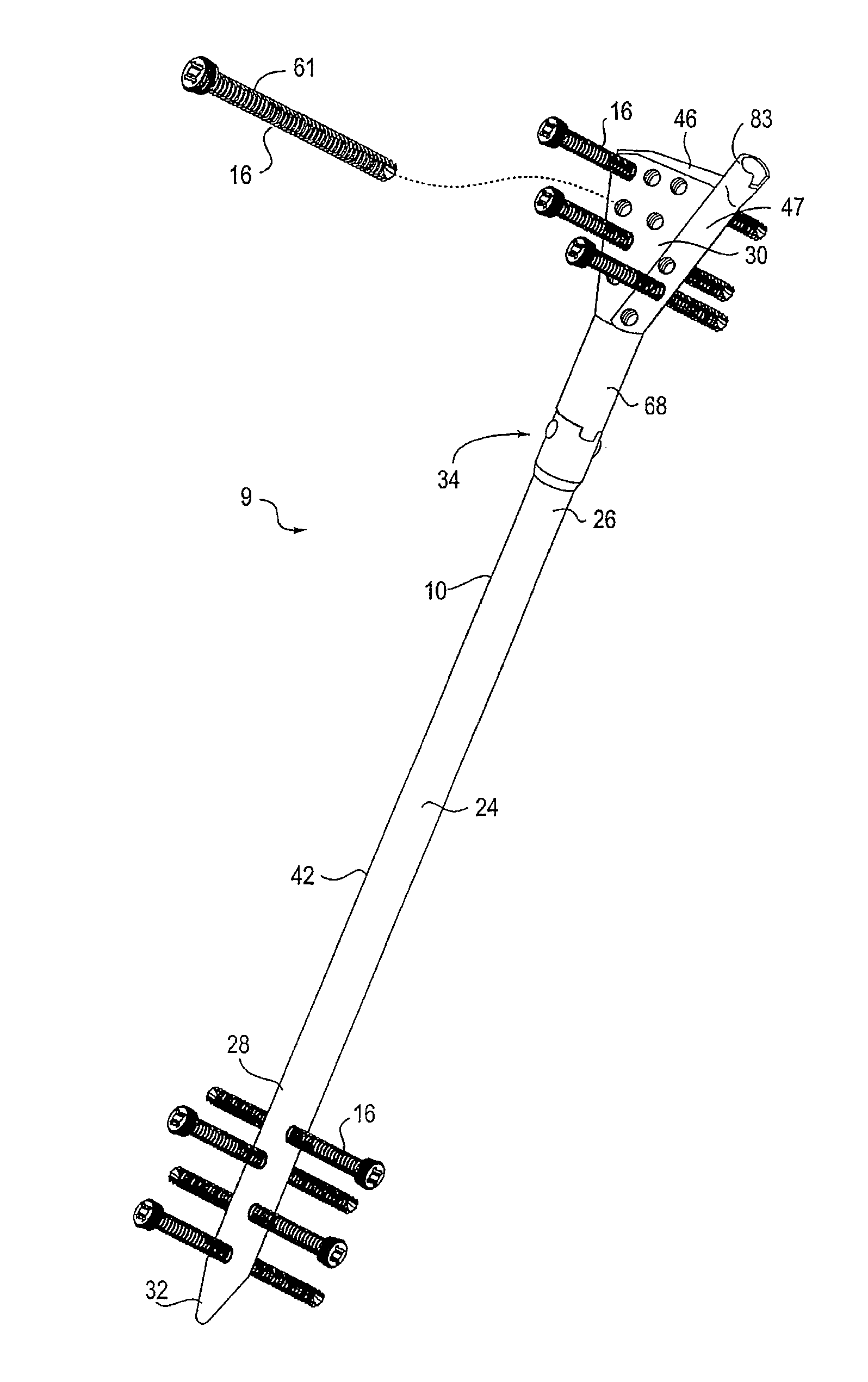
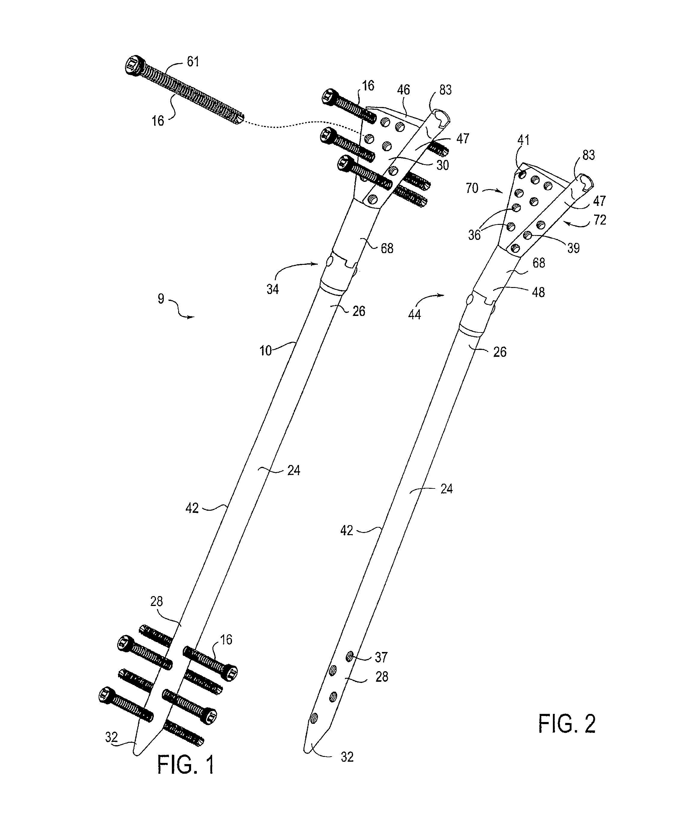
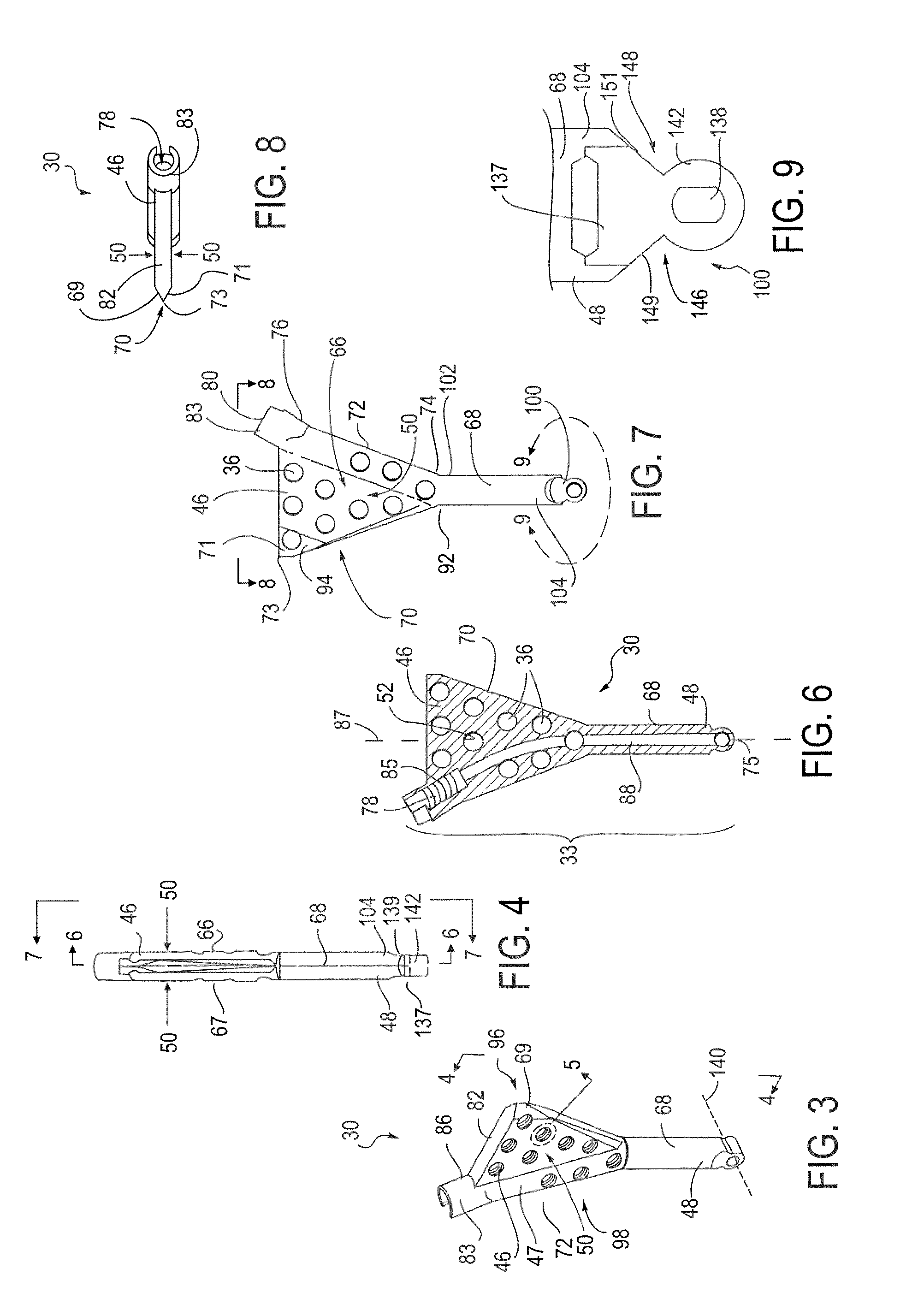
[0038]The figures and description herein describe an intramedullary bone repair system and device. More specifically, a percutaneous intramedullary bone repair system 9 is provided. In this system, the bone repair device 10 is inserted within the interior 12 of the bone 14 and secured in position using one or more fastening devices, such as screws 16. The intramedullary bone repair device 10 is adapted for placement or insertion into a bone 14. The bone 14 has a first end 18 and a second end 20, and a longitudinal axis 22 extending therebetween. The device 10 preferably extends along a longitudinal axis 22 of the bone 14 and is for use with a plurality of screws 16. The device 10 includes an elongate body, shaft or nail 24 having a proximal end 26 and a distal end 28. A head or plate 30 is seated in, and preferably pivotally coupled to the proximal end of the shaft 24. The distal end of the shaft 24 has a tapered end 32 for facilitating insertion of the shaft 24 along the longitudin...


PUM


Abstract

An intramedullary bone repair system and device for insertion into a bone extending along a longitudinal axis of the bone and for use with a plurality of screws. The bone repair device includes an elongate shaft and a head pivotally coupled to the proximal end of the shaft. A locking assembly is carried by the proximal end of the shaft and the head for rigidly coupling the shaft and the head together when the shaft and the head have been desirably positioned within the bone. The shaft and the head are provided with a plurality of threaded bores for receiving the plurality of screws to affix the shaft and head within the bone. A method for repair of a bone fracture using the bone repair device is also disclosed.

Description

SCOPE OF THE INVENTION[0001]The present invention relates to a bone repair assembly, and more particularly a device and method to repair bone fractures.BACKGROUND[0002]It is known to repair bone fractures using a plate. Typically, a plate is affixed to the side of a fractured bone. It is also known to repair bone fractures using a nail. Currently to fix a fracture of a long bone, such as the femur or tibia, two primary devices exists. To repair a bone fractured at the middle shaft component, or a shaft component within the middle part of the bone, a nail is most commonly used. The nail is inserted into the interior of the bone. The standard for repairing articular fractures, or fractures that go into the joint, or fractures within five centimeters of the joint, on the other hand involves the use and attachment of a plate to the side of the bone.[0003]Unfortunately, both devices suffer drawbacks. Plates attached to the side of a bone, which carry the weight of the patient formerly ca...

Claims


Application Information

Patent Timeline
Patent Type & Authority Patents(United States)
IPC IPC(8): A61B17/58
CPCA61B17/1725A61B17/7241A61B17/725A61B17/7283A61B17/8625A61B2017/00004A61B17/7275
Inventor MATITYAHU, AMIR M.
Owner ANTHEM ORTHOPAEDICS LLC
Why Eureka
Try Eureka