Sliding door apparatus having a damping mechanism

a technology of damping mechanism and sliding door, which is applied in the direction of doors/windows, doors/window fittings, constructions, etc., can solve the problems of complicated design and installation procedures of sliding door assemblies, and achieve the effect of simple design and quick installation

Active Publication Date: 2012-07-10
DIRTT ENVIRONMENTAL SOLUTIONS
View PDF32 Cites 29 Cited by
  • Summary
  • Abstract
  • Description
  • Claims
  • Application Information

AI Technical Summary

Benefits of technology

[0006]The present invention is directed toward providing an improved apparatus for a sliding door assembly. One objective of the present invention is to provide a sliding door assembly with an integrated slowdown mechanism. Another objective of the present invention is to provide a sliding door assembly with a simplified design. Yet another object of the present invention to provide a sliding door assembly that can be installed quickly and easily.
[0007]One or more of the stated objectives is accomplished by a sliding door assembly which utilizes a single catch or stop block, located at the approximate center point of the sliding door's support track, to slow the motion of the sliding door in either direction along the support track. The use of a single catch reduces the number of discrete parts that must be assembled during installation. The single catch also simplifies the design and construction of the sliding door assembly. Further, the single catch design allows the sliding door to travel the full length of the support track because there is no need for a braking mechanism between the sliding door and end of the support track. Further still, sliding doors assemblies can be mounted next to one another and the doors of the respective assemblies can meet without a gap.
[0008]One or more of the stated objectives is accomplished by a sliding door assembly which utilizes a mounting arm that attaches the sliding door assembly to an existing wall structure without the use of additional fasteners. The mounting arm simplifies the design and construction of the sliding door assembly, as well as the installation procedure.

Problems solved by technology

Two aspects of these sliding door assemblies in particular complicate their design and installation procedures.
Second, sliding door assemblies in the art employ discrete fastening means to secure the sliding door assemblies to a wall.

Method used


Image

  • Sliding door apparatus having a damping mechanism
  • Sliding door apparatus having a damping mechanism
  • Sliding door apparatus having a damping mechanism

Examples


Embodiment Construction

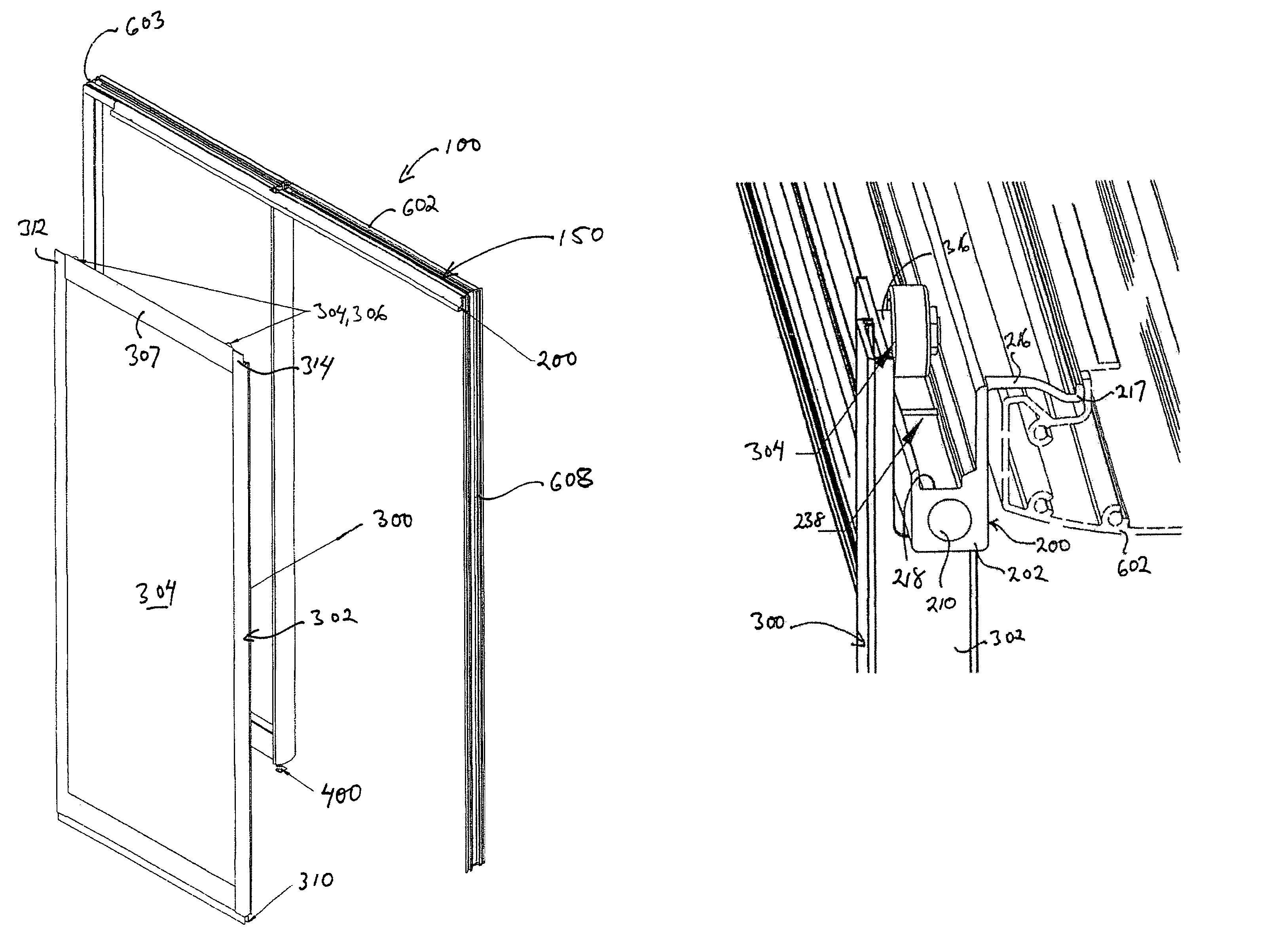
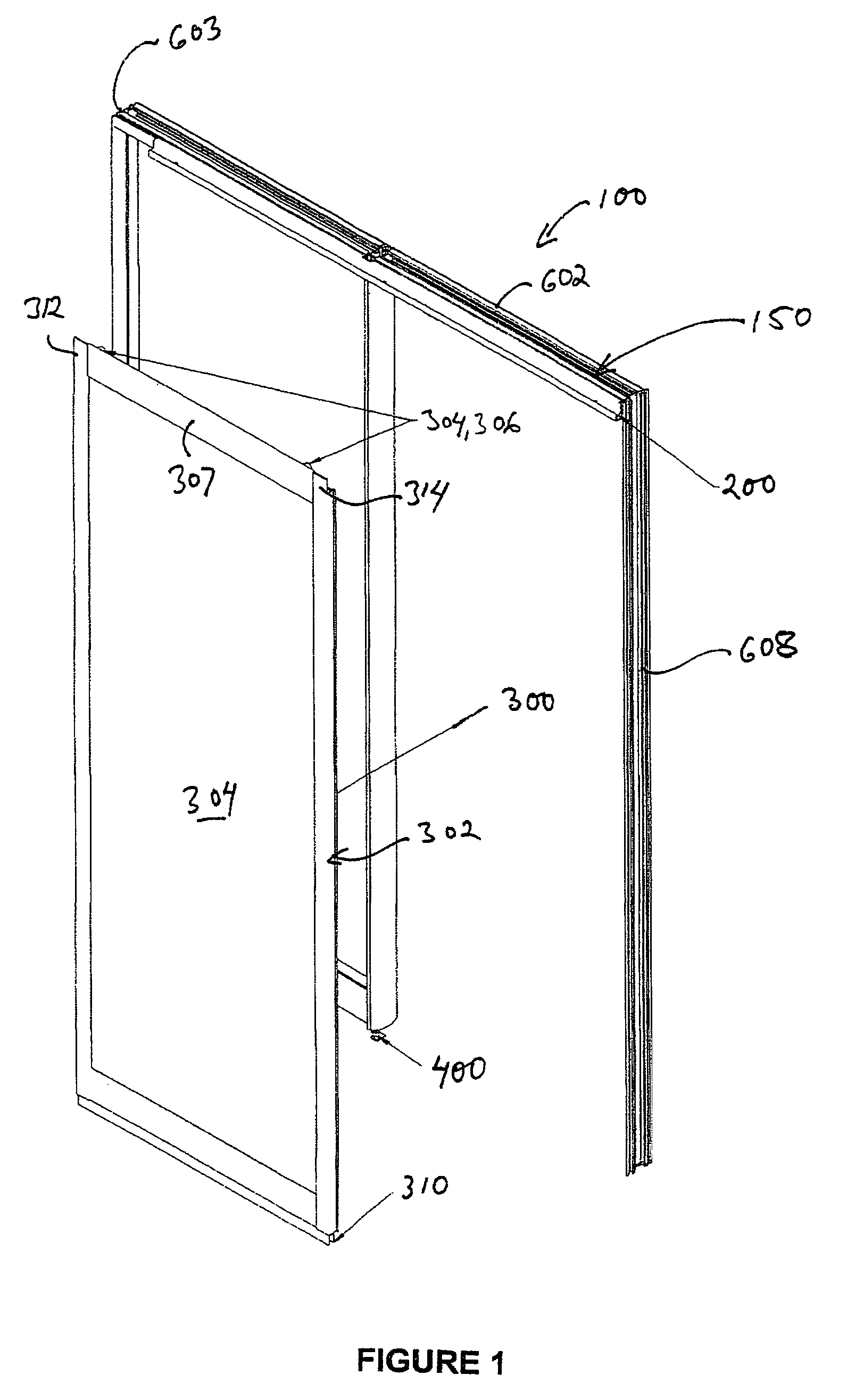
[0027]With reference to FIG. 1, the sliding door assembly 100 of the present invention generally comprises a sliding door 300, a sliding door frame 150 consisting of an upper horizontal stringer 602 and spaced apart vertical stringers 608 and a support track assembly 200 that releasably connects to frame 150 and which also supports door 300 for back and forth movement while providing progressive damping or braking as the door approaches its fully opened and closed positions and a floor assembly 400.

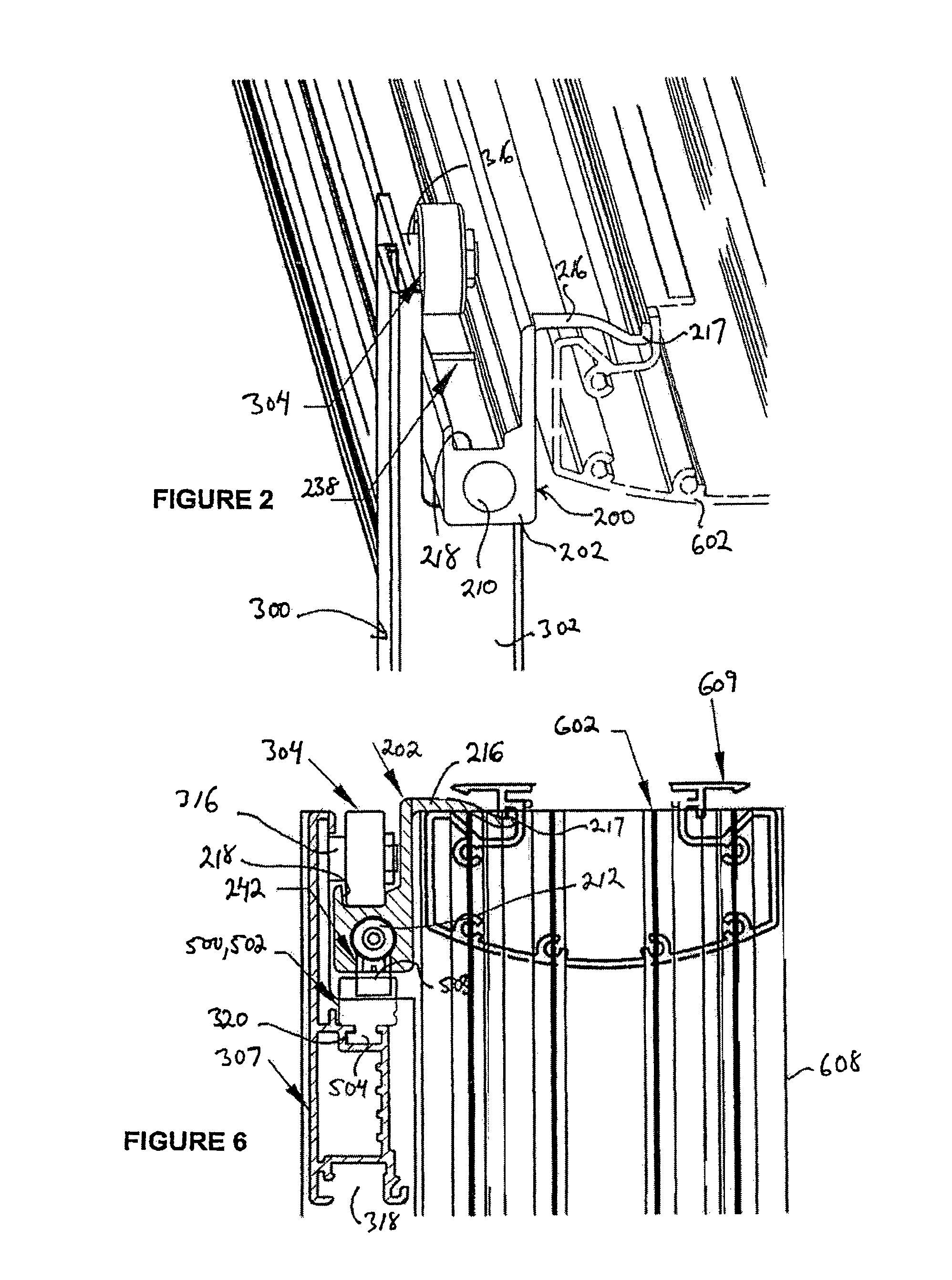
[0028]FIG. 2 provides a more detailed view of the connection between door 300, support track assembly 200 and stringer 602 of frame 150. Support track assembly 200“hooks” into stringer 602 for a cantilevered connection as will be described more fully below. Door 300 is then suspended from support track assembly 200 by means of rollers 304, 306 that are received into a roller channel 218 in assembly 200. The rollers are free to roll from side to side in channel 218 for opening and closing ...


PUM


Abstract

A sliding door apparatus for opening and closing an opening in a wall. A sliding door apparatus including a longitudinally extending track member mountable along an upper edge of an opening and a door movably mountable on the track member for sliding movement thereon between opened and closed positions. A damping structure is disposed within the track member and is actuatable in response to the sliding movement of the door to break the door's movement as it approaches its opened and closed positions.

Description

CROSS-REFERENCE TO RELATED APPLICATIONS[0001]The subject patent application claims priority to U.S. Provisional Application Serial No. 60 / 648,435 which was filed on Feb. 1, 2005, the entirety of which is incorporated herein by reference.FIELD OF THE INVENTION[0002]The present invention relates generally to sliding door assemblies.BACKGROUND OF THE INVENTION[0003]The present invention relates to a sliding door assembly for closing an opening in a wall, wherein the sliding door is provided with rollers mounted on its upper edge for movement in a plane parallel to and spaced from the wall. The rollers are supported by and roll along a support track which is secured to the wall.[0004]Sliding door assemblies in the art comparable to the present invention have complicated designs and complicated installation procedures requiring the assembly of several different components. Two aspects of these sliding door assemblies in particular complicate their design and installation procedures. Firs...

Claims


Application Information

Patent Timeline
Patent Type & Authority Patents(United States)
IPC IPC(8): E05F11/54
CPCE05F5/10E06B3/4618E06B3/4636E05F5/003E05Y2201/21E05Y2201/256E05Y2201/264
Inventor GOSLING, GEOFFSMED, MOGENS
Owner DIRTT ENVIRONMENTAL SOLUTIONS
Why Eureka
Try Eureka