
Rapid image rendering on dual-modulator displays

Active Publication Date: 2012-07-10
DOLBY LAB LICENSING CORP
View PDF30 Cites 30 Cited by
  • Summary
  • Abstract
  • Description
  • Claims
  • Application Information

AI Technical Summary

Problems solved by technology

The task of deriving from image data signals to control a light source layer and display layer can be computationally expensive.
Performance limitations of the processor can undesirably limit the rate at which successive image frames can be displayed.
This can distract the observer and negatively affect the observer's image viewing experience.

Method used


Image

  • Rapid image rendering on dual-modulator displays
  • Rapid image rendering on dual-modulator displays
  • Rapid image rendering on dual-modulator displays

Examples


Embodiment Construction

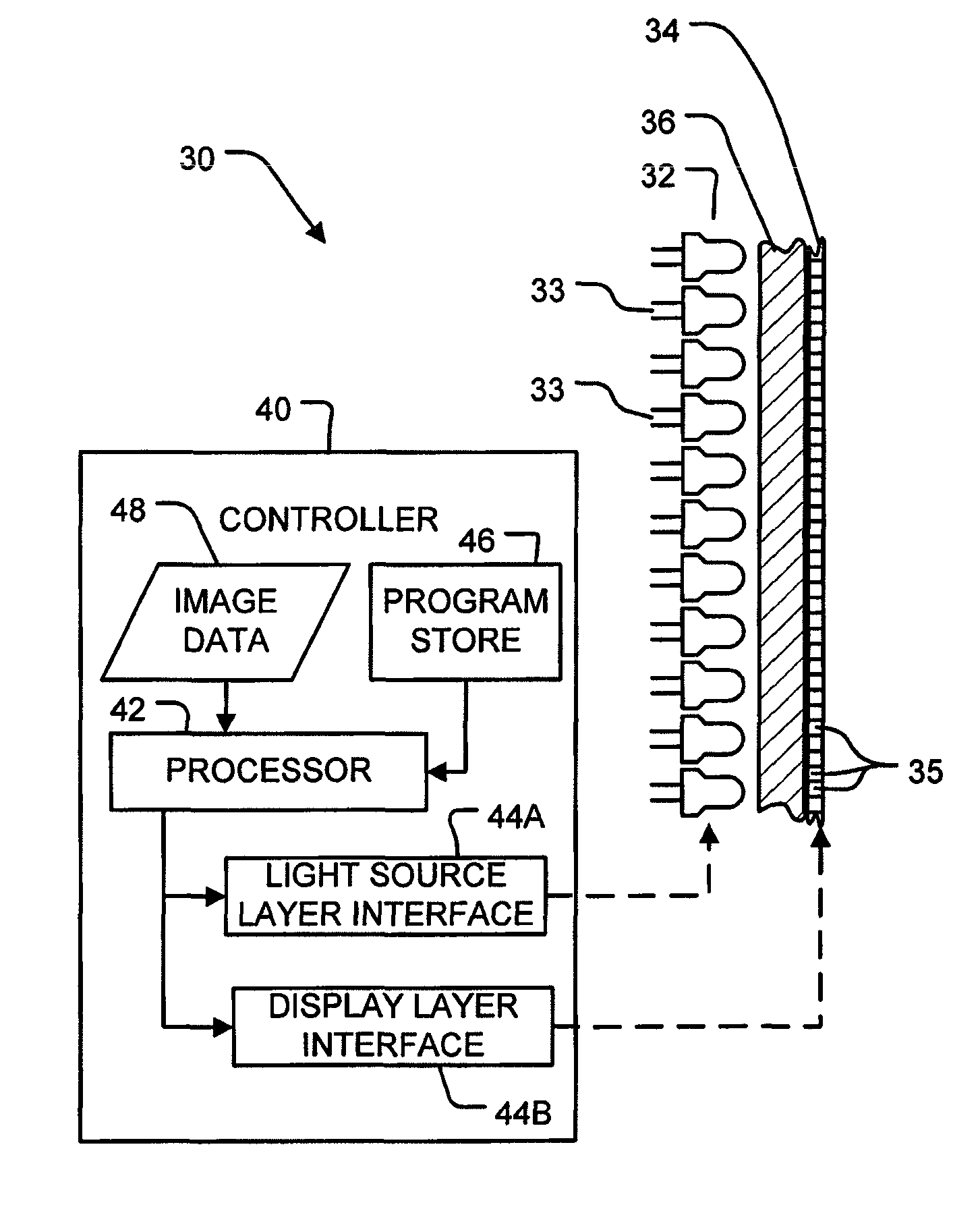
[0059]FIGS. 6 to 9 show some example embodiments of the invention. FIG. 6 shows a display 30 comprising a modulated light source layer 32 and a display layer 34. Light source layer 32 may comprise, for example:[0060]an array of controllable light sources such as LEDs;[0061]a fixed-intensity light source and a light modulator disposed to spatially modulate the intensity of light from the light source;[0062]some combination of these.

In the illustrated embodiment, light source layer 32 comprises an array of LEDs 33.

[0063]Display layer 34 comprises a light modulator that further spatially modulates the intensity of light incident on display layer 34 from light source layer 32. Display layer 34 may comprise an LCD panel or other transmission-type light modulator, for example. Display layer 34 typically has a resolution higher than a resolution of light source layer 32. Optical structures 36 suitable for carrying light from light source layer 32 to display layer 34 may be provided between...


PUM


Abstract

Apparatus and methods are provided that employ one or more of a variety of techniques for reducing the time required to display high resolution images on a high dynamic range display having a light source layer and a display layer. In one technique, the image resolution is reduced, an effective luminance pattern is determined for the reduced resolution image, and the resolution of the effective luminance pattern is then increased to the resolution of the display layer. In another technique, the light source layer's point spread function is decomposed into a plurality of components, and an effective luminance pattern is determined for each component. The effective luminance patterns are then combined to produce a total effective luminance pattern. Additional image display time reduction techniques are provided.

Description

CROSS-REFERENCE TO RELATED APPLICATION[0001]This application claims priority from U.S. patent application No. 60 / 591,829 filed on 27 Jul. 2004 and entitled RAPID FRAME RENDERING FOR HIGH DYNAMIC RANGE DISPLAYS; and PCT Patent Application No. PCT / CA2005 / 000807, filed on 27 May 2005 and entitled RAPID IMAGE RENDERING ON DUAL-MODULATOR DISPLAYS. For purposes of the United States of America, this application claims the benefit under 35 U.S.C. §119, 120, 121 and 365, as applicable, of U.S. patent application No. 60 / 591,829 filed on 27 Jul. 2004 and entitled RAPID FRAME RENDERING FOR HIGH DYNAMIC RANGE DISPLAYS; and PCT Patent Application No. PCT / CA2005 / 000807, filed on 27 May 2005 and entitled RAPID IMAGE RENDERING ON DUAL-MODULATOR DISPLAYS.TECHNICAL FIELD[0002]This invention pertains to systems and methods for displaying images on displays of the type that have two modulators. A first modulator produces a light pattern and a second modulator modulates the light pattern produced by the ...

Claims


Application Information

Patent Timeline
IPC IPC(8): G09G5/02
CPCG09G3/3426G09G3/36G09G2320/0238G09G2340/0428G06T3/4007
Inventor WHITEHEAD, LORNE A.SEETZEN, HELGEWARD, GREGORY JOHNHEIDRICH, WOLFGANG
Owner DOLBY LAB LICENSING CORP
Learn More