Plane light source apparatus and prism sheet and liquid crystal display apparatus

a light source and prism technology, applied in the direction of instruments, optics, static indicating devices, etc., can solve the problems of inability to achieve the low power consumption effect, the weight of the light guide plate becomes very heavy, and the efficiency of light emitted from the light source cannot be improved. , to achieve the effect of improving the efficiency of light emitted, reducing the number of point light sources, and low power consumption

Inactive Publication Date: 2007-12-06
MIKUNI ELECTORON CO LTD
View PDF10 Cites 30 Cited by
  • Summary
  • Abstract
  • Description
  • Claims
  • Application Information

AI Technical Summary

Benefits of technology

[0021] Therefore, it is a primary objective of the present invention employs a downward prism sheet as shown in FIG. 2 to use the light emitted from a linear light source or a point light source effectively to produce a plane light source for a large LCD TV, and achieve the effects of lowering the power consumption, reducing the thickness, and providing a field order driving function.
[0051] In the backlight system of the optical system applied in the present invention, the diffused light is emitted from the direction of a polarization axis of a polarizer that intersects with the direction of the LCD panel. Compared with the foregoing diffused backlight, the light diffusion along the direction of ±45 degrees of the polarization axis can be reduced, such that when an IPS or a FFS horizontal field LCD panel uses a backlight of the present invention, it is not necessary to use the expensive optical compensation film to lower the cost significantly and enhance the contrast.

Problems solved by technology

To maintain a uniform light intensity of a light source, the straight-below type light source apparatus has to use a diffuser with a high diffusion effect, and thus it cannot improve the efficiency of using the light emitted from a light source.
Theoretically, the straight-below type light source apparatus changes the light coming from a light source into a diffused light, and an optical system using a prism sheet for condensing the light cannot achieve the low power consumption effect.
When the size of the panel is increased, the weight of the light guide plate becomes very heavy and loses the advantage of a light-weighted the liquid crystal display apparatus.
If the aforementioned cold cathode fluorescent lamp (CCFL) is within 30 inches, such method can give a very limited effect.
If a downward prism sheet with better light efficiency is used and its light source is built on the two long sides of the panel only, then the brightness cannot be improved as well as the straight-below type light source apparatus.
To provide a field order driven large LCD TV display apparatus, the lateral edge-light type light source apparatus divides the screen into blocks, but it is difficult to control the light emitting area precisely.
If the straight-below type plane light source apparatus uses the point light source of the LED for the manufacture, the optical system as shown in FIG. 1 will require many LEDs that will increase the power consumption and will not be able to lower the installation cost.

Method used


Image

  • Plane light source apparatus and prism sheet and liquid crystal display apparatus
  • Plane light source apparatus and prism sheet and liquid crystal display apparatus
  • Plane light source apparatus and prism sheet and liquid crystal display apparatus

Examples


embodiment 1

[0129] Referring to FIGS. 47 to 50 and 52 to 54 for a planar view of a linear light source or a row of point light sources in accordance with Embodiment 1 of the present invention, all types of light sources are arranged into a row at the x-axis direction of a light emitting portion for emitting a strip light precisely. The smaller the light emitting portion, the more accurate is the emitting angle. Therefore, the shape of the emitting portion is different from the light emitting portion of the foregoing LED chip. For white color LEDs, the required quantity of rectangular chips as shown in FIG. 54 can be less than the quantity of square chips as shown in FIG. 47, and thus the installation cost can be lowered. Since the precision of installing a rectangular chip at a cooling substrate can be improved, therefore it is preferably to use the rectangular chip for the LED in the present invention.

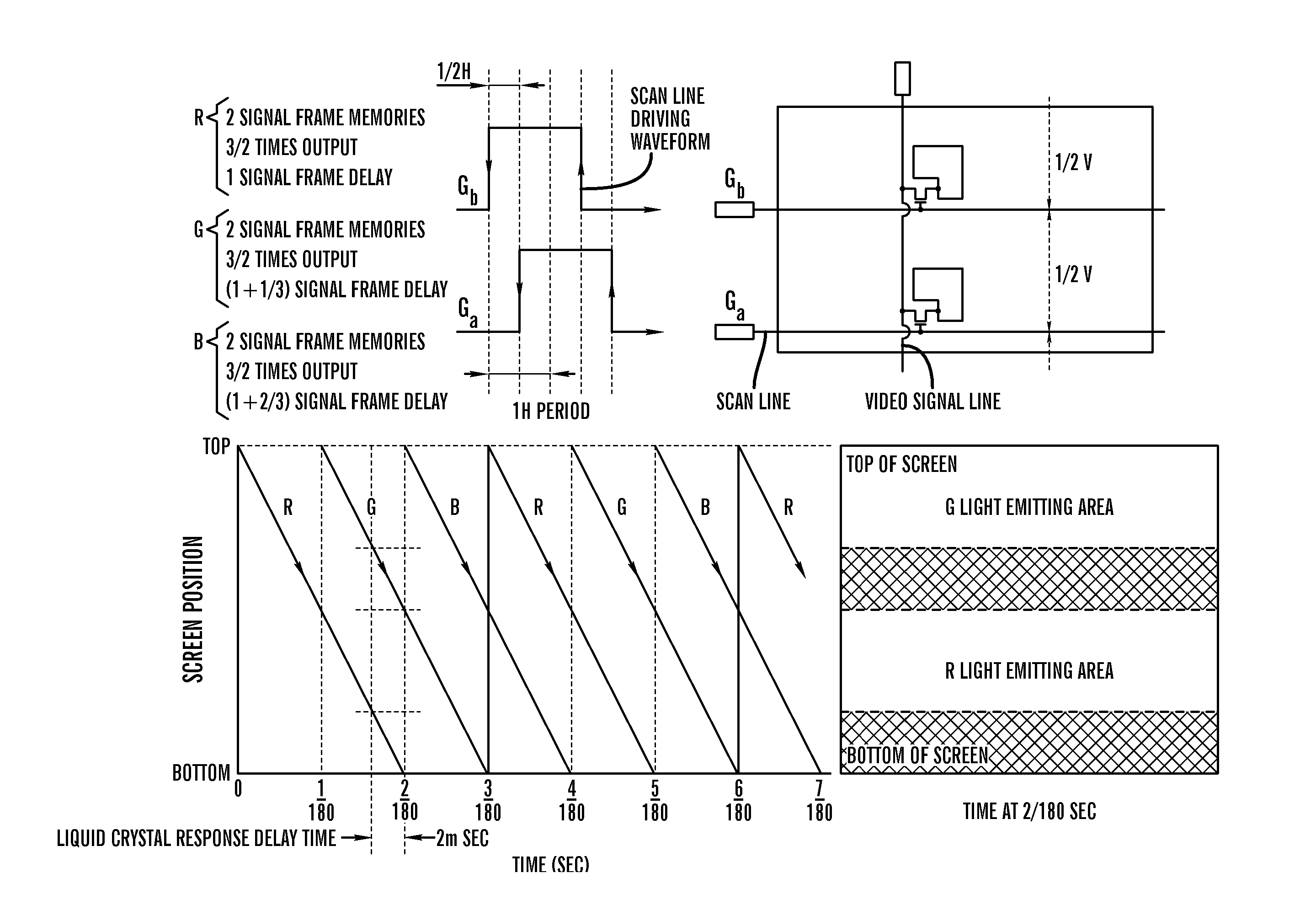
[0130] The field order driving method adopted by a linear light source or row of point light ...

embodiment 2

[0131] Referring to FIGS. 13, 18 to 23, 30 and 31 for Embodiment 2 of the present invention, the strip light of a plurality of semi-cylindrical lenses or a semi-cylindrical Fresnel lens is used for producing an optical unit. This embodiment of the present invention uses two semi-cylindrical lenses or three semi-cylindrical lenses, but there are cost and weight issues, and thus it is preferably to use two semi-cylindrical lenses for the invention. To provide two semi-cylindrical lenses with the same optical axis (or z-axis), a light emitting portion of a linear light source or a light emitting portion of a row of point light sources is set along the z-axis. In this embodiment as shown in FIGS. 20 to 23 and 30, a plurality of downward prisms is arranged on a prism sheet for projecting a strip light in one direction. If the strip lights are parallel with each other, each strip light cannot be superimposed, and thus the invention as shown in FIGS. 13 and 31 is characterized in that the ...

embodiment 7

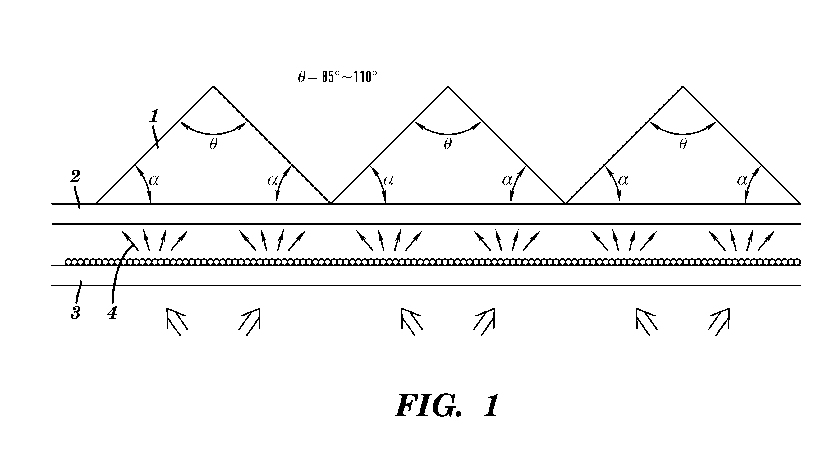
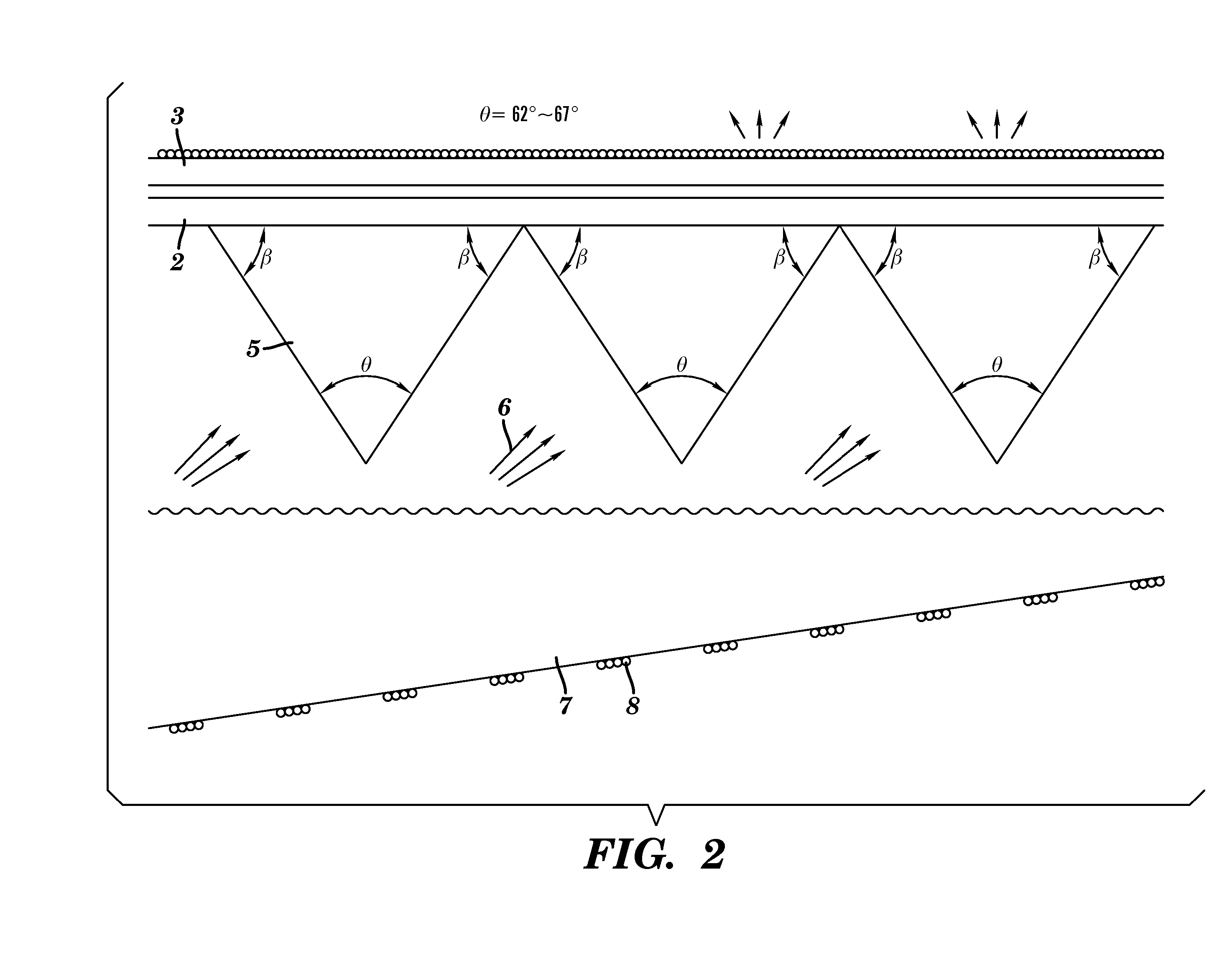
[0140] Referring to FIGS. 41 to 43 for cross-sectional views of a backlight using a prism of a basic unit of a prism sheet comprised a plurality of prism and having a light deflection function in accordance with Embodiment 7 of the present invention, FIG. 41 shows a surface of a substrate film of the prism sheet, and a light is emitted perpendicularly from the surface of the substrate film after the light is incident into a surface of the substrate film at an incident angle of 12 degrees. The light is emitted perpendicularly from the surface of the substrate film as shown in FIG. 43 after a light is incident at an incident angle of 16 degrees. The light is emitted perpendicularly from the surface of the substrate film as shown in FIG. 42 after a light is incident at an incident angle of 19 degrees. Any incident light of a prism is reflected completely from an oblique surface of a backside of the prism and opposite to the surface of the incident light, and the light is polarized in a...


PUM

PropertyMeasurementUnit
incident angleaaaaaaaaaa

Abstract

The present invention provides a LCD panel with an isosceles triangular cross-section having a base angle of 50 to 55 degrees, and an incident angle equal to 10 to 24 degrees. Several triangular prisms are installed downwardly on a prism sheet by using the base angle as a vertex angle for controlling the light to be travel in a parallel direction, and incident in a direction perpendicular to an oblique surface of a smaller surface of the prism. The oblique surface of a larger surface of the prism reflects the incident light completely and projects the light perpendicular to the bottom of the prism. An optical system provides a backlight for a liquid crystal display apparatus and an anisotropic diffuser installed at an orthogonal direction of a prism has a diffusion function such that the light can be diffused by the LCD panel and the two orthogonally installed polarizers.

Description

FIELD OF THE INVENTION [0001] The present invention relates to a plane light source apparatus of a backlight system for a super large liquid crystal display television (LCD TV), and a prism sheet having a light diffraction function used in the plane light source apparatus, and more particularly to a method of using a row of linear light sources or a point light source to control the light emitting direction precisely and a light with a precise emitting direction for installing a light deflection component to an LCD TV panel and enhancing an incident direction with a maximum ratio. BACKGROUND OF THE INVENTION [0002] Basically, a plane light source apparatus used in a backlight system of a liquid crystal display apparatus can be divided into two types: a straight-below type plane light source apparatus that installs a light source directly below an LCD panel and a lateral edge-light type plane light source apparatus that installs a light source at a lateral side of an LCD panel and ad...

Claims


Application Information

Patent Timeline
Patent Type & Authority Applications(United States)
IPC IPC(8): G09G3/36G02F1/13357
CPCG02F1/133603G02F2001/133607G09G2310/06G09G3/3426G09G2310/0235G09G3/342G02F1/133607G02B5/045G02F1/1335G09G3/3413
Inventor TANAKA, SAKAE
Owner MIKUNI ELECTORON CO LTD
Why Eureka
Try Eureka