
Lens having extended depth of focus, method for designing the same, and optical system having the same

a technology of depth of focus and axisymmetric lens, applied in the field of optical technology, can solve the problems of deteriorating the performance of the edof system, generating undesired image duplication, and general optical system using thin lens approximation is inappropriate for use, so as to simplify the point spread function and design easy

Active Publication Date: 2009-11-12
SAMSUNG ELECTRONICS CO LTD
View PDF5 Cites 30 Cited by
  • Summary
  • Abstract
  • Description
  • Claims
  • Application Information

AI Technical Summary

Benefits of technology

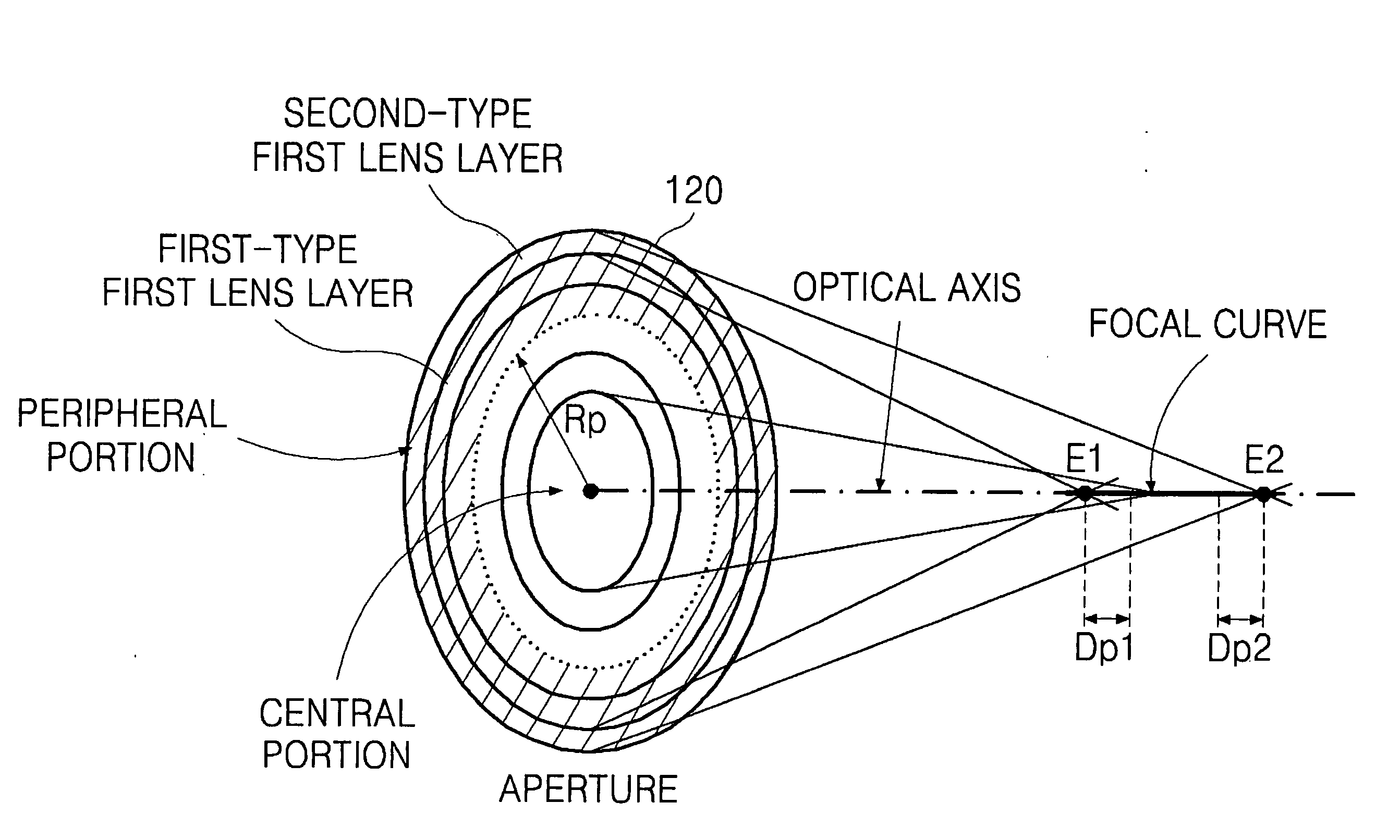
[0012]Example embodiments provide a lens having an extended depth of focus that can at least one of: generate a clear image regardless of a distance from an object and has symmetry, simplify a point spread function, provide continuity of a lens surface, and easy design, as well as an optical system having the lens.
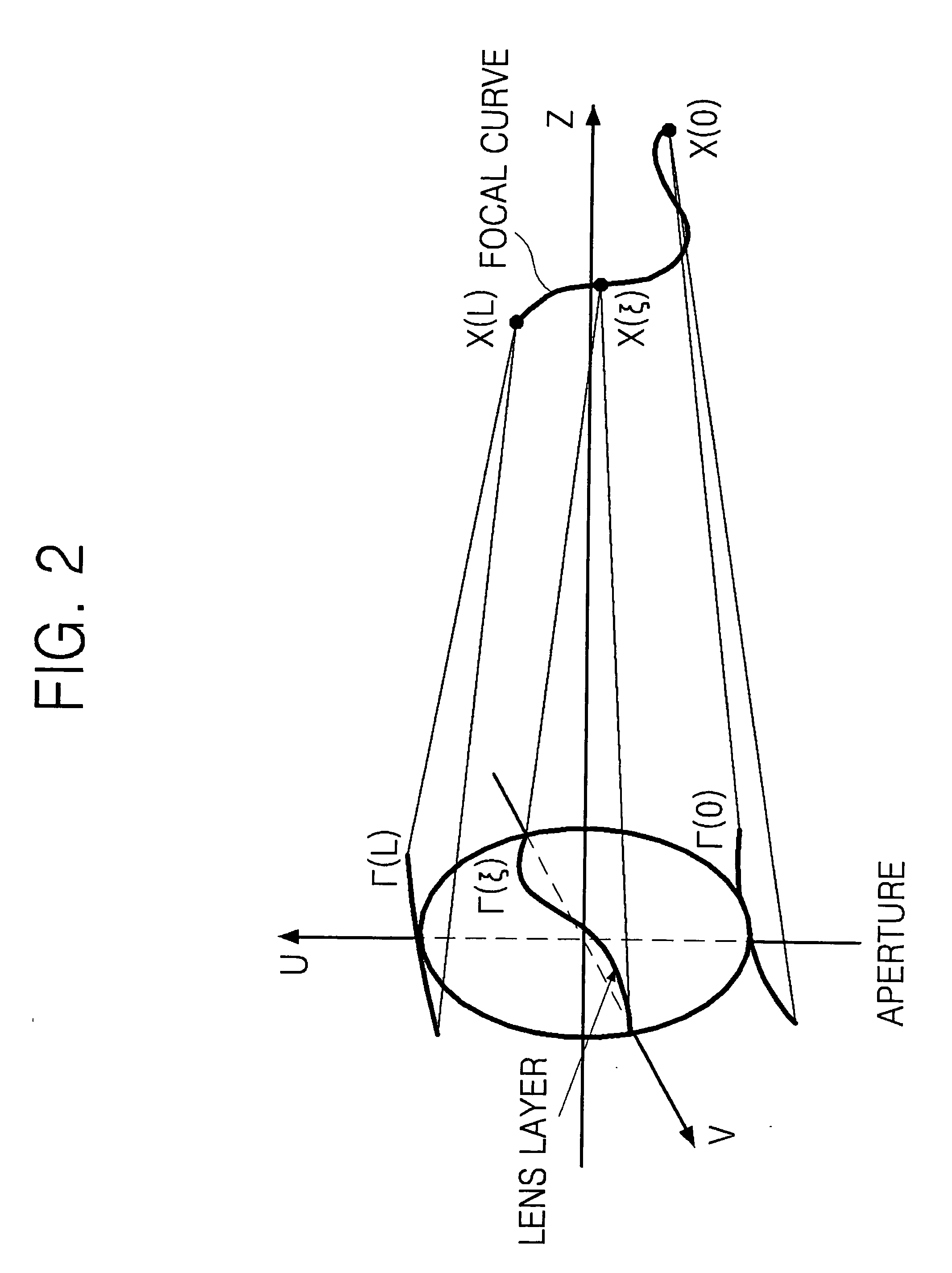
[0017]The sections of the focal curve corresponding to the lens layers may be overlapped with one another. A thickness of each of the corresponding at least one lens layer of the plurality of lens layers may control a distribution of intensity of a light field of any one of the plurality of sections of the focal curve.

Problems solved by technology

A general optical system using thin lens approximation is inappropriate for use in a variety of industrial fields using laser material processing, lithography, or light projection and image processing.
The uniform distribution of the portions and the sub-portions may generate undesired image duplication.
However, the optical system has problems with discontinuity, asymmetry, and randomization that may deteriorate the performance of the EDOF system.
However, this structure is appropriate for the aspherical lens, but inappropriate for a portion exceeding the optical performance of an eye.

Method used


Image

  • Lens having extended depth of focus, method for designing the same, and optical system having the same
  • Lens having extended depth of focus, method for designing the same, and optical system having the same
  • Lens having extended depth of focus, method for designing the same, and optical system having the same

Examples


Embodiment Construction

[0029]Example embodiments will now be described more fully with reference to the accompanying drawings, in which example embodiments are shown. Example embodiments may, however, be embodied in many different forms and should not be construed as being limited to the embodiments set forth herein; rather, these embodiments are provided so that this disclosure will be thorough and complete, and will fully convey the concept of example embodiments to those of ordinary skill in the art. In the drawings, the thicknesses of layers and regions are exaggerated for clarity. Like reference numerals in the drawings denote like elements, and thus their description will be omitted.

[0030]It will be understood that when an element is referred to as being “connected” or “coupled” to another element, it can be directly connected or coupled to the other element or intervening elements may be present. In contrast, when an element is referred to as being “directly connected” or “directly coupled” to anot...


PUM


Abstract

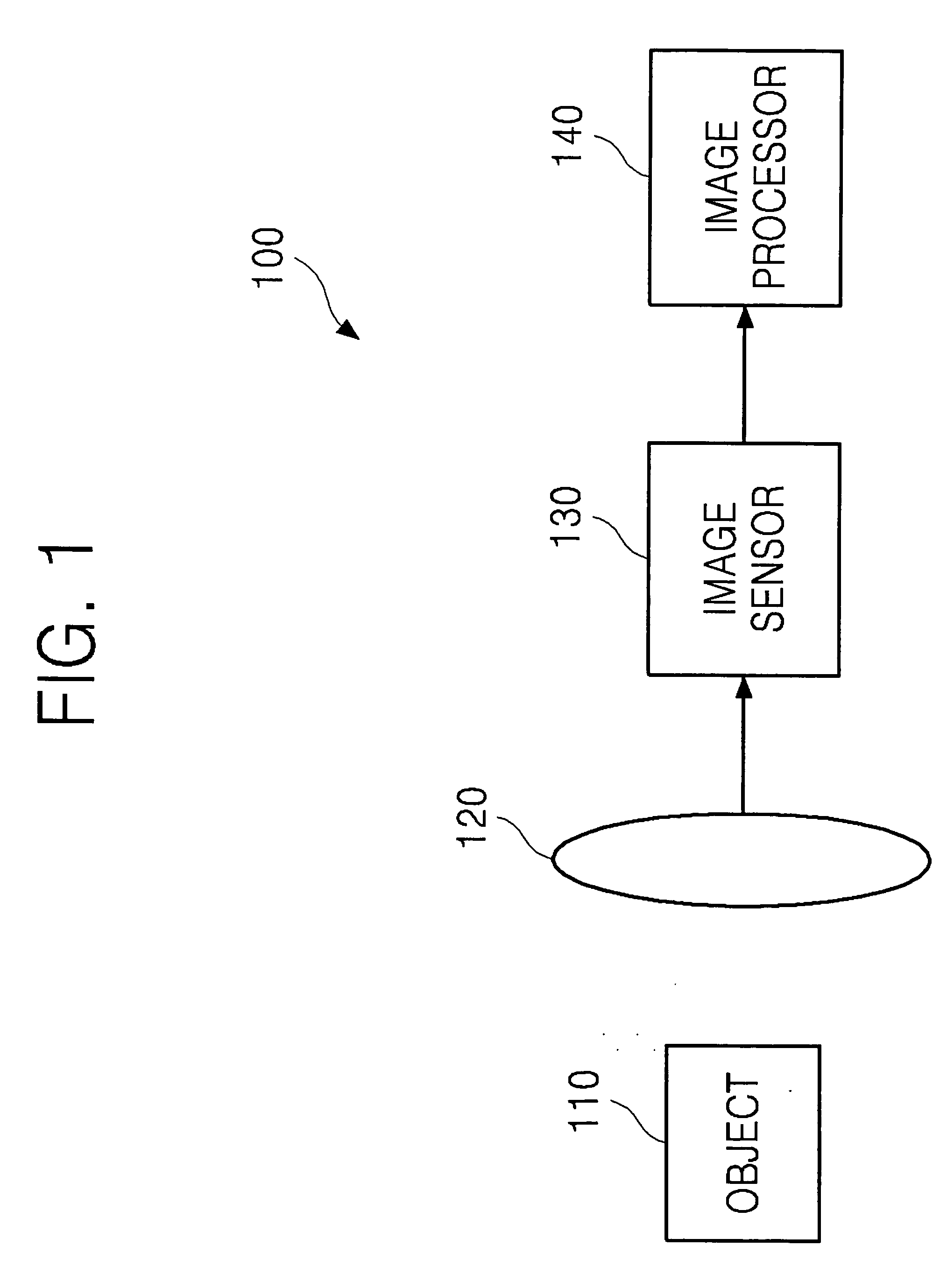
The lens includes a plurality of lens layers, each lens layer being axi-symmetric and having an extended depth of focus to focus light in a corresponding section of a focal curve in the form of a straight line located on an optical axis. In the optical system, light is focused on an optical axis to obtain a clear image in a wide distance range between a camera and an object. The optical system has a point spread function that is simpler and more symmetric. That is, the optical system provides improved continuity of a lens surface and easiness and flexibility in optical designing.

Description

PRIORITY STATEMENT[0001]This application claims priority under 35 U.S.C. §119 to Korean Patent Application No. 10-2008-0043428, filed on May 9, 2008, in the Korean Intellectual Property Office (KIPO), the entire contents of which are incorporated herein by reference.BACKGROUND[0002]1. Field of the Invention[0003]Example embodiments relate to optical technology, and more particularly, to an axi-symmetric lens having an extended depth of focus, and an optical system having the axi-symmetric lens.[0004]2. Description of the Related Art[0005]In general, a depth of focus (DOF) is one of the major characteristics of an optical system defining a distance range between an object plane and a lens, or a distance range between a lens and an image plane, to obtain a clear image. The major factors determining the DOF include aperture size and aberration of various optical lenses.[0006]A general optical system using thin lens approximation is inappropriate for use in a variety of industrial field...

Claims


Application Information

Patent Timeline
IPC IPC(8): G02B3/00
CPCG02B3/08G02B27/0075G03B7/04H04N23/00
Inventor GETMAN, ALEXANDERLUKYANOV, ANDREY
Owner SAMSUNG ELECTRONICS CO LTD
Learn More