
Method And System For Magnetic Resonance Imaging Using Nitrogen-Vacancy Centers

a magnetic resonance imaging and nitrogen-vacancy center technology, applied in the field of magnetic resonance imaging, can solve the problems of insufficient imaging on molecular and atomic scales, limited spatial resolution of conventional mri systems, and inability to perform conventional mri on sub-micron length scales, etc., to achieve the effect of improving magnetic imaging

Inactive Publication Date: 2017-02-09
PRESIDENT & FELLOWS OF HARVARD COLLEGE +1
View PDF1 Cites 33 Cited by
  • Summary
  • Abstract
  • Description
  • Claims
  • Application Information

AI Technical Summary

Benefits of technology

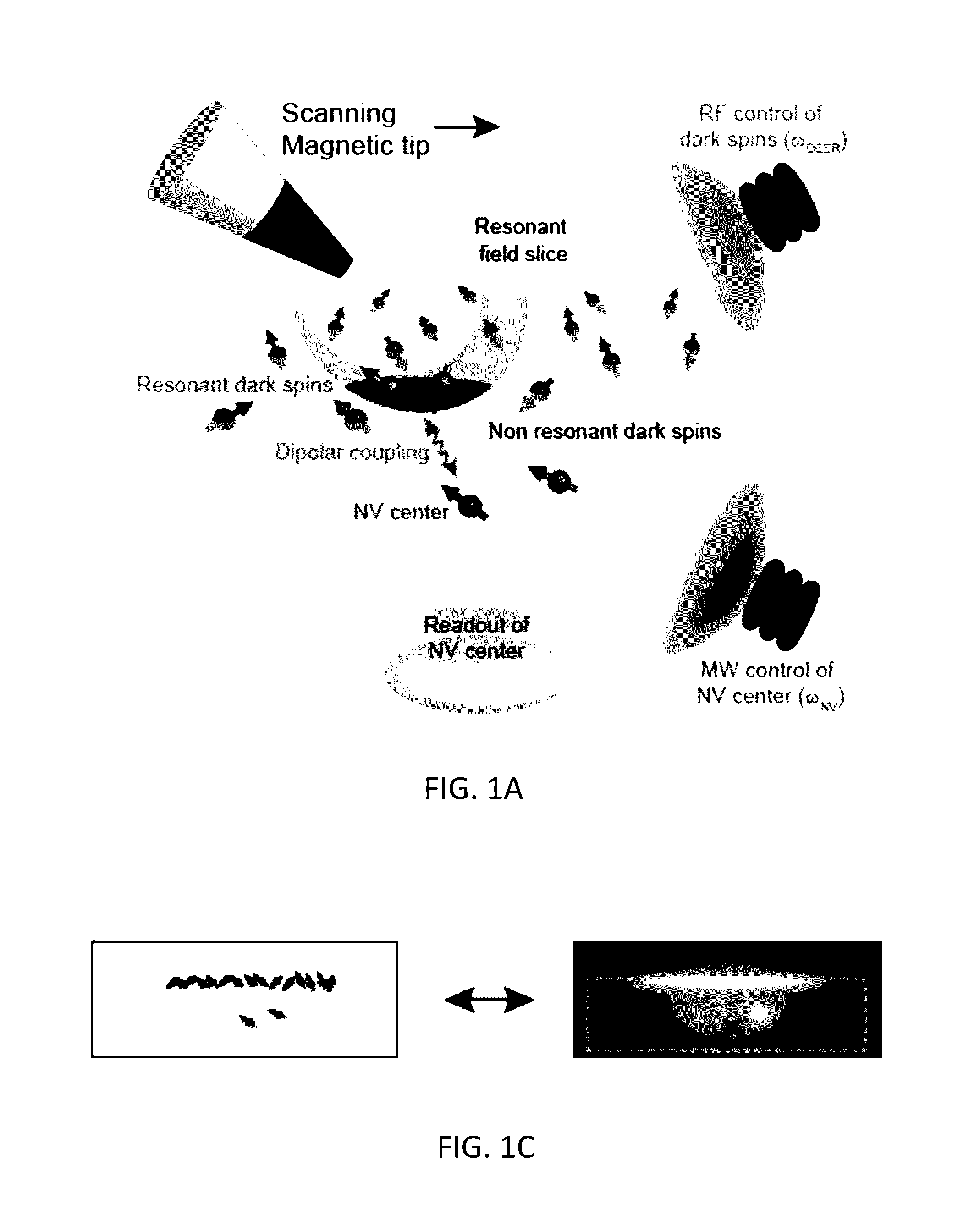
The present invention is a method and system for magnetic resonance imaging that can measure the distribution of dark spins in a sample with sub-nanometer resolution in three dimensions, using a single electron-spin sensor. This technique is compatible with various developed methods for bringing imaging targets close to the sensor. The invention utilizes a diamond chip with a shallowly planted nitrogen-vacancy center and a microscope to control the position of the sample for magnetic detection. The method can measure non-resonant target dark spins and provide a three-dimensional mapping of their distribution. This new technique offers a unique combination of resolution and single-spin sensitivity, and can be applied to different systems for magnetic imaging.

Problems solved by technology

However, spatial resolution in conventional MRI systems is limited to tens of microns, which is insufficient for imaging on molecular and atomic scales.
Performing conventional MRI on sub-micron length scales, however, is not possible with present systems and methods because macroscopically generated magnetic-field gradients limit spatial resolution, and inductive detection schemes suffer from significant thermal noise.
However for most MRI applications, measurements must be taken near room temperature, and nearly all targets of interest contain optically ‘dark’ spins that are unpolarized or weakly polarized.

Method used


Image

  • Method And System For Magnetic Resonance Imaging Using Nitrogen-Vacancy Centers
  • Method And System For Magnetic Resonance Imaging Using Nitrogen-Vacancy Centers
  • Method And System For Magnetic Resonance Imaging Using Nitrogen-Vacancy Centers

Examples


Embodiment Construction

[0025]The method and system of the present invention combine an NV magnetometer with scanning magnetic-field gradients using an atomic-force microscope. An exemplary NV magnetometer is described in U.S. Pat. No. 8,547,090, entitled “Electron Sin Based Enhancement of Magnetometer Sensitivity.” In a preferred embodiment of the present invention, individual shallowly implanted NV centers (nominal depth of 10 nm) are placed in the focus of a confocal microscope so that the NV electronic spin can be initialized by optical pumping, used as a sensor to measure nearby dark spins, and read out using time-dependent fluorescence. See, A. Gruber, et al., “Scanning Confocal Optical Microscopy and Magnetic Resonance on Single Defect Centers,” Science 276, 2012 (1997). To image the 3D distribution of dark spins via NV-MRI, a local magnetic-field gradient is applied with a scanning magnetic tip. The magnetic tip provides a narrow spatial volume (a ‘resonant slice’) in which dark spins are on resona...


PUM


Abstract

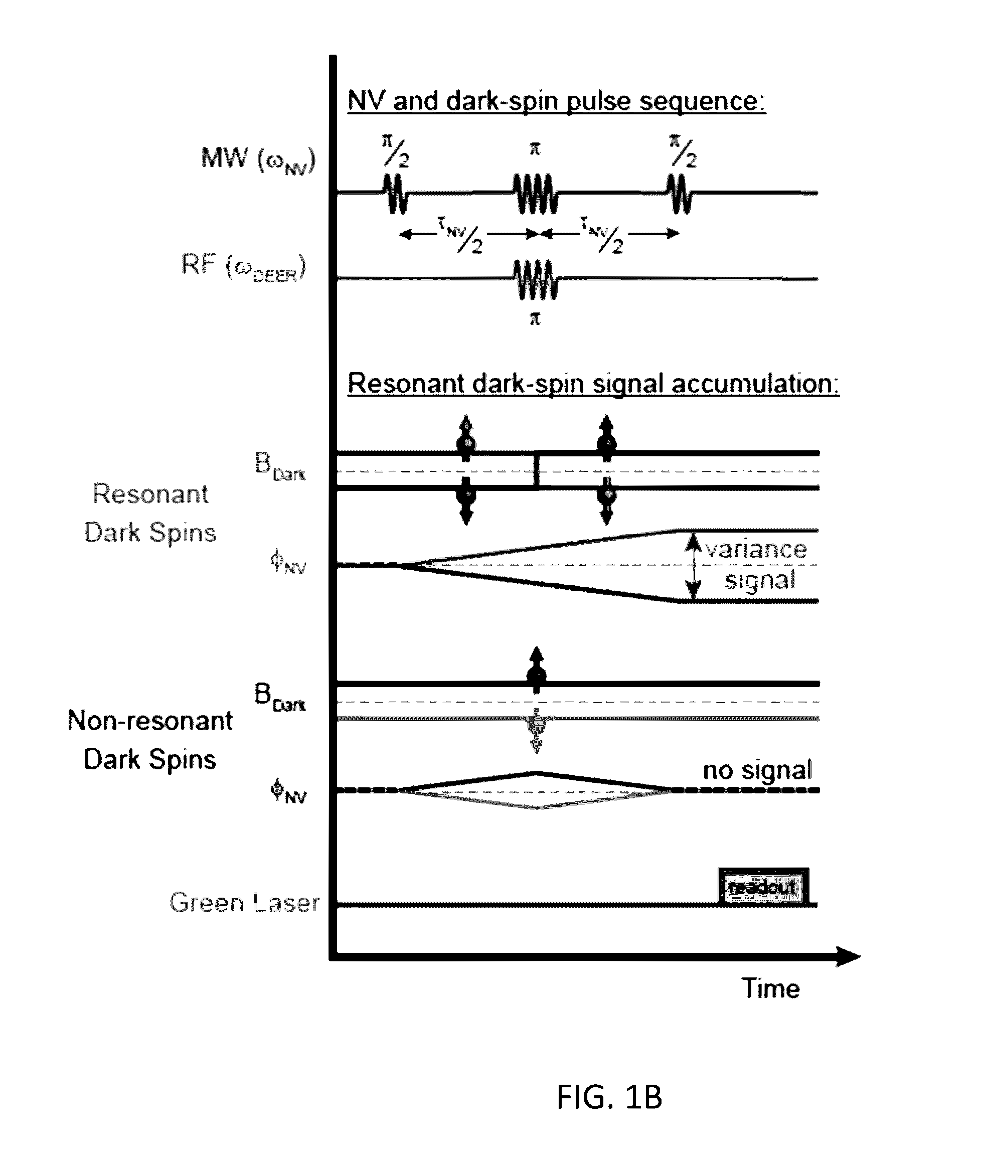
A method for performing sub-nanometer three-dimensional magnetic resonance imaging of a sample under ambient conditions using a diamond having at least one shallowly planted nitrogen-vacancy (NV) center. A driving radio-frequency (RF) signal and a microwave signal are applied to provide independent control of the NV spin and the target dark spins. A magnetic-field gradient is applied to the sample with a scanning magnetic tip to provide a narrow spatial volume in which the target dark electronic spins are on resonance with the driving RF field. The sample is controllably scanned by moving the magnetic tip to systematically bring non-resonant target dark spins into resonance with RF signal. The dark spins are measured and mapped by detecting magnetic resonance of said nitrogen-vacancy center at each of said different magnetic tip positions. The dark-spin point-spread-function for imaging the dark spins is directly measured by the NV center.

Description

CROSS-REFERENCE TO RELATED APPLICATIONS[0001]The present application claims the benefit of the filing date of U.S. Provisional Patent Application Ser. No. 62 / 103,234 filed by the present inventors on Jan. 14, 2015.[0002]The aforementioned provisional patent application is hereby incorporated by reference in its entirety.STATEMENT REGARDING FEDERALLY SPONSORED RESEARCH OR DEVELOPMENT[0003]This invention was made with government support under Contract No. HR0011-11-C-0073 awarded by the Defense Advanced Research Projects Agency (DARPA), Contract No. 5710003135 awarded by Office of Naval Research and Contract No. HR0011-09-1-0005 awarded by the Defense Advanced Research Projects Agency (DARPA). The government has certain rights in the invention.BACKGROUND OF THE INVENTION[0004]Field of the Invention[0005]The present invention relates to magnetic resonance imaging (MRI), and more particularly, to methods and systems for sub-nanometer magnetic resonance imaging.[0006]Brief Description of...

Claims


Application Information

Patent Timeline
Patent Type & Authority Applications(United States)
IPC IPC(8): G01Q60/52G01R33/24G01R33/62
CPCG01Q60/52G01R33/24G01R33/62G01N24/12G01R33/48
Inventor YACOBI, AMIRGRINOLDS, MICHAELWARNER, MARCDE GREVE, KRISTIAANDOVZHENKO, YULIYA
Owner PRESIDENT & FELLOWS OF HARVARD COLLEGE
Learn More