
Image formation apparatus including hot-roll type fixing device and method for determining malfunction of temperature sensor in the same

a technology of image formation apparatus and fixing device, which is applied in the direction of electrographic process apparatus, instruments, optics, etc., can solve the problems of disadvantageous increase in size, complex as a whole, and inability to use contact type temperature sensor as described above, so as to accurately determine whether the malfunction occurs.

Active Publication Date: 2012-07-10
KONICA MINOLTA BUSINESS TECH INC
View PDF15 Cites 2 Cited by
  • Summary
  • Abstract
  • Description
  • Claims
  • Application Information

AI Technical Summary

Benefits of technology

"The present invention provides an image formation apparatus that can accurately determine whether malfunction occurs or not in a temperature sensor detecting the surface temperature of a heat roller. This is achieved by using a first and second temperature sensor to detect the temperature at a position on the heat roller, and a temperature estimation portion to determine the surface temperature of the heat roller based on the input values from the temperature sensors. The apparatus also includes a determination portion that determines whether a malfunction occurs or not in the temperature sensors based on the temporal behavior of the multidimensional data during a temperature increase of the heat roller. The invention can provide a more accurate and reliable basis for identifying malfunctions in the temperature sensor, which can help improve the overall performance and reliability of the image formation apparatus."

Problems solved by technology

In such a contact-type temperature sensor, since the temperature detection is performed directly, detection errors resulting from attachment of dust, toner, paper dust and the like in the apparatus are relatively few.
By contrast, recently, the surface of the heat roller is covered with a soft material and the surface of the heat roller receives a scratch by being contact with the temperature sensor, so that the contact type temperature sensor as described above cannot be used.
This image formation apparatus disclosed in Japanese Laid-Open Patent Publication No. 2000-259033 requires a mechanism that allows the contact-type surface temperature detection means to come into abutment with or go away from the fixing roller and is disadvantageously increased in size and complicated as a whole.
Therefore, if dust, toner, paper dust or the like attaches to the temperature compensation means (e.g. thermistor) causing the entire offset in the output thereof, malfunctions cannot be detected.
Furthermore, in the image formation apparatus disclosed in Japanese Laid-Open Patent Publication No. 2006-047411, since the correction temperature is determined based on the time required for the temperature sensed by the non-contact type temperature sensor to yield a prescribed temperature increase, proper correction cannot be performed if the entire offset is caused in the output of the non-contact type sensor, as described above.
Moreover, correction is performed based on a temperature change between two points of the sensed temperature, so that such correction that reflects the behavior of the sensed temperature during the course cannot be performed.

Method used


Image

  • Image formation apparatus including hot-roll type fixing device and method for determining malfunction of temperature sensor in the same
  • Image formation apparatus including hot-roll type fixing device and method for determining malfunction of temperature sensor in the same
  • Image formation apparatus including hot-roll type fixing device and method for determining malfunction of temperature sensor in the same

Examples


first embodiment

[0062][First Embodiment]

[0063](Configuration of Image Formation Apparatus)

[0064]The present invention is applied to an image formation apparatus including a hot-roll type fixing device and is applicable to any image formation apparatus as long as it includes a heat roller that can be increased in temperature. In the following description, as a typical example of the image formation apparatus in accordance with the present invention, MFP (Multi Function Peripheral) equipped with a plurality of functions such as a copy function, a print function, a facsimile function and a scanner function is shown. However, the present invention is also applicable to a photocopier only including a copy function or a printer only including a print function.

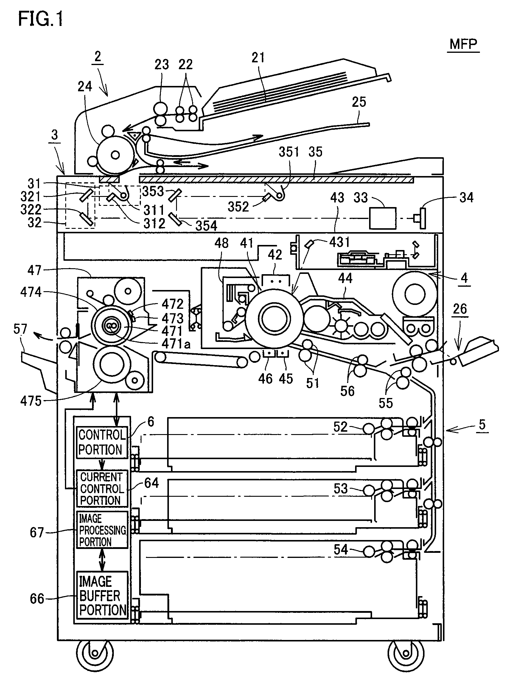
[0065]Referring to FIG. 1, an image formation apparatus MFP in accordance with a first embodiment of the present invention includes an automatic document feeder portion 2, an image scanning portion 3, an image formation portion 4, and a paper-feedin...

second embodiment

[0165][Second Embodiment]

[0166]In the foregoing first embodiment, image formation apparatus MFP employing the differential type temperature estimation method has been described. In the present embodiment, image formation apparatus MFP employing an independent type temperature estimation method will be described.

[0167]The schematic configuration of image formation apparatus MFP in accordance with the present embodiment is similar to the schematic configuration of image formation apparatus MFP in accordance with the first embodiment shown in FIG. 1 and therefore the detailed description will not be repeated.

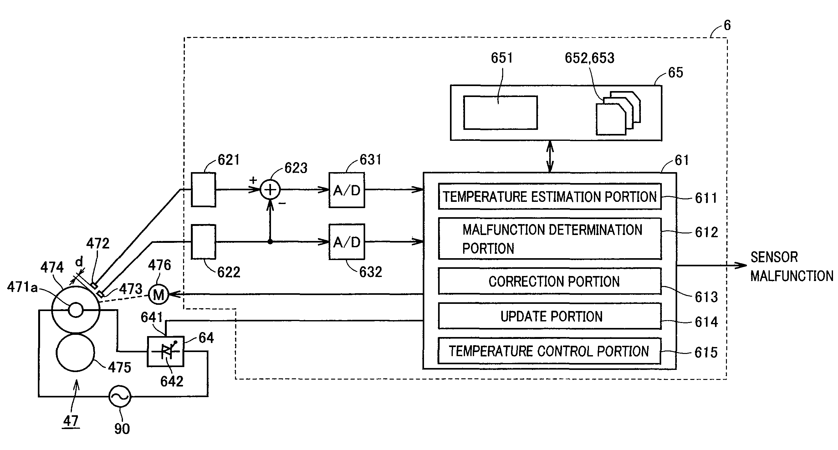
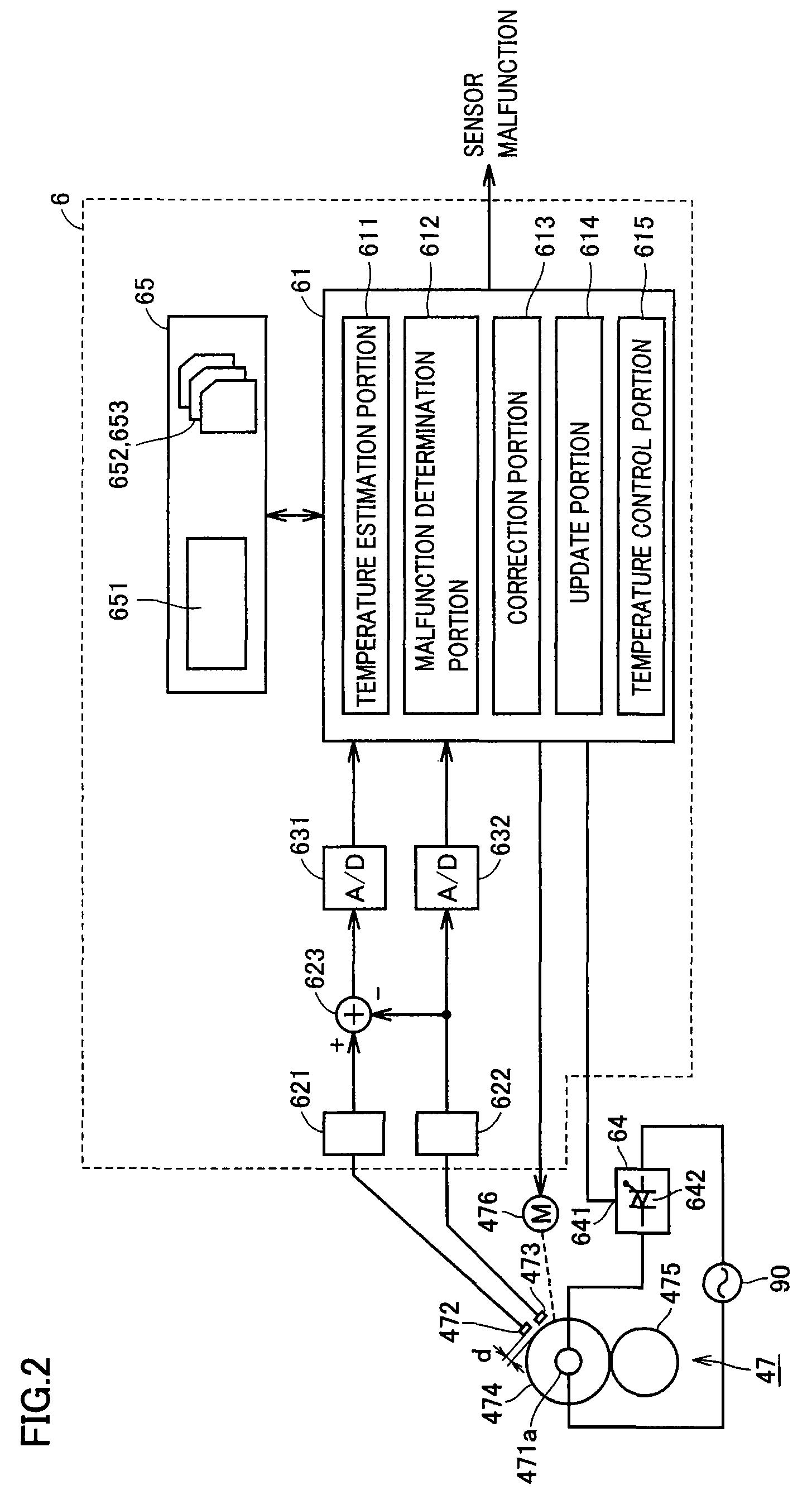
[0168]Referring to FIG. 15, a control structure concerning heat roller 474 in accordance with the second embodiment of the present invention is formed by removing subtraction portion 623 in the control structure shown in FIG. 2 and storing a temperature table 651#, a transition destination table 652# and a transition time table 653# in storage portion 65, in place of temperature ta...


PUM


Abstract

A control portion determines whether a malfunction occurs or not in a roller temperature sensor and an ambient temperature sensor by comparing a trajectory (temporal behavior) actually created by two-dimensional data on a temperature table with a target trajectory. In other words, the control portion successively integrates a prescribed weight for each transition from one element to the adjacent element corresponding to a trajectory of two-dimensional data on the temperature table, and determines whether or not a malfunction occurs in the roller temperature sensor and the ambient temperature sensor, based on the integrated weight.

Description

[0001]This application is based on Japanese Patent Application No. 2007-247244 filed with the Japan Patent Office on Sep. 25, 2007, the entire content of which is hereby incorporated by reference.BACKGROUND OF THE INVENTION[0002]1. Field of the Invention[0003]The present invention relates to an image formation apparatus including a hot-roll type fixing device and a method for determining malfunction of a temperature sensor in the same, and more particularly to determination as to whether malfunction occurs or not in a non-contact type temperature sensor.[0004]2. Description of the Related Art[0005]In image formation apparatuses such as photocopiers or printers, after a toner image is transferred onto a sheet, heat and pressure are applied to this toner image using a heat roller to fix the image on the sheet. In order to perform such a fixing process more appropriately, temperature management of the heat roller is important. Conventionally, in order to perform such heat roller temper...

Claims


Application Information

Patent Timeline
Patent Type & Authority Patents(United States)
IPC IPC(8): G03G15/20
CPCG03G15/2039G03G2215/00772
Inventor TAKANO, MASAHITO
Owner KONICA MINOLTA BUSINESS TECH INC
Learn More