Close formation flight positioning system using air data measurements

Inactive Publication Date: 2012-07-10
AIR FORCE THE US SEC THE
View PDF8 Cites 28 Cited by
  • Summary
  • Abstract
  • Description
  • Claims
  • Application Information

AI Technical Summary

Benefits of technology

[0014]The invention is a method for determining the relative position of an aircraft flying behind another while in close proximity, for example the receiver aircraft while aerial refueling, or follower aircraft in a tw

Problems solved by technology

Many other approaches have been propose or tried for this problem, but they either require data from both

Method used


Image

  • Close formation flight positioning system using air data measurements
  • Close formation flight positioning system using air data measurements
  • Close formation flight positioning system using air data measurements

Examples


Embodiment Construction

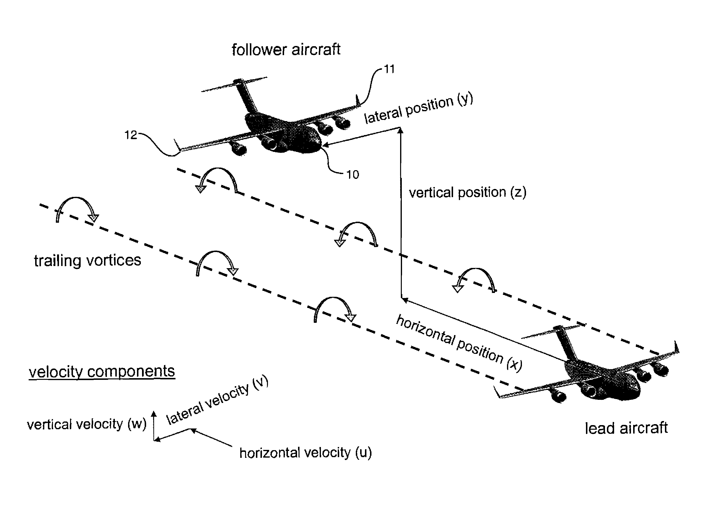
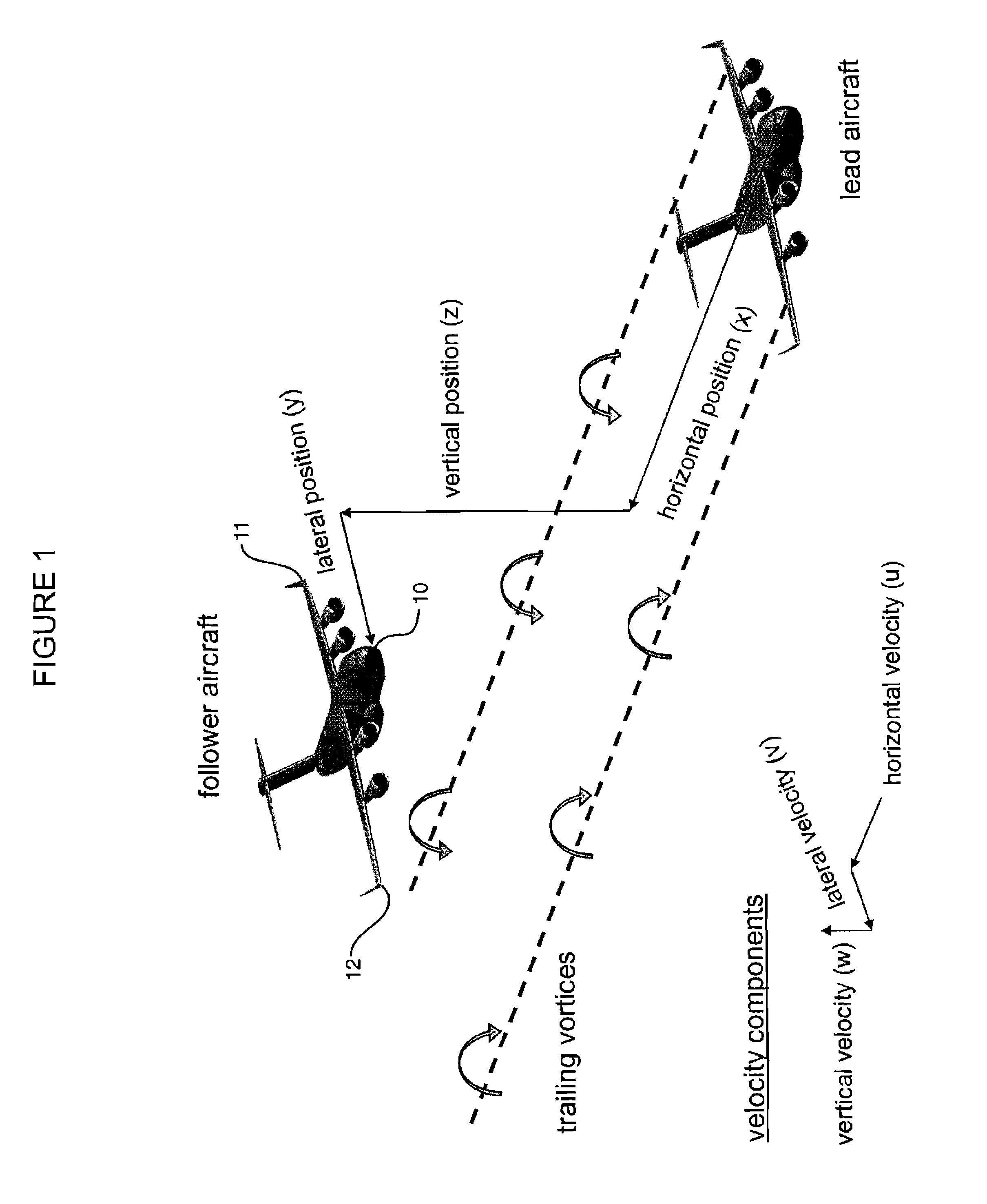
[0025]Lift on a wing is developed from the difference in air pressure on the upper and lower surfaces. The air pressure on the lower surface is higher than that on the upper surface, resulting in a lift force. At the wing tips, the flow curls around the tips, establishing a circulatory motion that trails downstream, resulting in a vortex whose axis is aligned with the flight path of the lead aircraft. A “horseshoe vortex” is a well established model for this trailing vortex structure. With the horseshoe vortex model, the wing itself is replaced by a bound vortex that is connected to each tip vortex thereby forming a horseshoe or U-shaped vortex. Near the center of these vortices, very high local velocities are present that decrease in air velocity magnitude as the radial distance from the center of the vortex increases. The magnitude of the velocities is proportional to the strength (Γ) of the vortex. The strength is directly proportional to the weight of the aircraft (W), divided b...


PUM


Abstract

A close formation flight positioning system uses only air data measurements without a data link. The wake vortex of a lead aircraft generates horizontal, vertical and lateral induced velocities that vary with horizontal, vertical and lateral position from its wing. Two or more laterally or vertically separated air data sensors on a follower aircraft measure impact pressure, angle of attack and angle of sideslip, which are converted to horizontal, vertical and lateral velocity components. By comparing these velocity component measurements, using the distance between the sensors on the follower aircraft and the wing span of the lead aircraft, the distance from the follower to the lead aircraft can be determined. If weight, speed and altitude of the lead aircraft are known, then two sensors on the follower aircraft are sufficient to determine relative positions. If those conditions are not known, then three sensors on the follower aircraft are needed.

Description

RIGHTS OF THE GOVERNMENT[0001]The invention described herein may be manufactured and used by or for the Government of the United States for all governmental purposes without the payment of any royalty.BACKGROUND OF THE INVENTION[0002]The invention relates to a close formation flight positioning system using air data measurements. Military aircraft fly in formation for a variety of reasons. In some of these formations, the aircraft are sufficiently close to one another that the trailing wake from the lead aircraft affects the aerodynamic characteristics of the follower aircraft. This situation is commonly termed “close formation flight”. One example of close formation flight is aerial refueling, where a receiver aircraft flies behind and below a tanker aircraft. Close formation flight can also be used for drag reduction, with follower aircraft flying in the beneficial upwash generated by the leaders, as is common in migratory birds.[0003]It is very difficult for pilots to maintain th...

Claims


Application Information

Patent Timeline
IPC IPC(8): G01C23/00
CPCB64D39/00G01C21/00G08G5/0052G05D1/104
Inventor BLAKE, WILLIAM B.
Owner AIR FORCE THE US SEC THE
Why Eureka
Try Eureka