Telescopically rotatable mop

a rotary mop and rotor technology, applied in the field of rotor rotation of rotors, can solve the problems of inconvenient operation, endanger the safety of users, and obvious tiresome mopping, and achieve the effects of reducing labor intensity, reducing operation failures, and increasing service li

Active Publication Date: 2012-07-17
TUO SHEN INT
View PDF10 Cites 32 Cited by
  • Summary
  • Abstract
  • Description
  • Claims
  • Application Information

AI Technical Summary

Benefits of technology

[0005]An object of the invention is to provide a telescopically rotatable mop that permits a convenient operation with less effort when the internal and external rods rotate in a telescopic way. In this way, the operation failure may be minimized and the service life may be increased.
[0015]wherein the engaging element is constructed as a cylindrical body with the middle and lower parts secured to the inside of the internal rod, and an annular element rotatable clockwise and counterclockwise at 360° is mounted on the top portion of the engaging element projecting in an exposed manner from the internal rod, and the external diameter D1 of the annular element is greater than the external diameter D2 of the internal rod, but smaller than is almost the same to the internal diameter φ1 of the external rod;wherein the length L1 of the driving element 50 is smaller than the length L2 of the inside of the engaging element; andwherein the bottom of the fixing cap is extended and secured to the opening of the engaging element in such a way that a gap S is provided between the fixing cap and the top of the actuating element, and the fixing cap includes at the top thereof a projecting flange (whose external diameter is greater than the external diameter D2 of the internal rod, but smaller than the external diameter D1 of the annular element) for positioning the annular element on the periphery of the top portion of the engaging element without affecting the rotation of the annular element within the external rod.

Problems solved by technology

After a mop has been used, it is necessary to wring dirty water from mop fabrics (or cotton strips) of the mop before soaking clean water again to facilitate washing a floor, and mopping is obviously a tiresome job.
Although the aforementioned device can improve the inconvenient way of wringing the mop fabrics by hands, yet the operation still requires a user to step on the pedal continuously by one foot, and keep the user's body in balance by another foot.
Such arrangement not only involves an inconvenient operation, but also endangers the safety of users when the users fail to stand stably or fall.

Method used


Image

  • Telescopically rotatable mop
  • Telescopically rotatable mop
  • Telescopically rotatable mop

Examples


Embodiment Construction

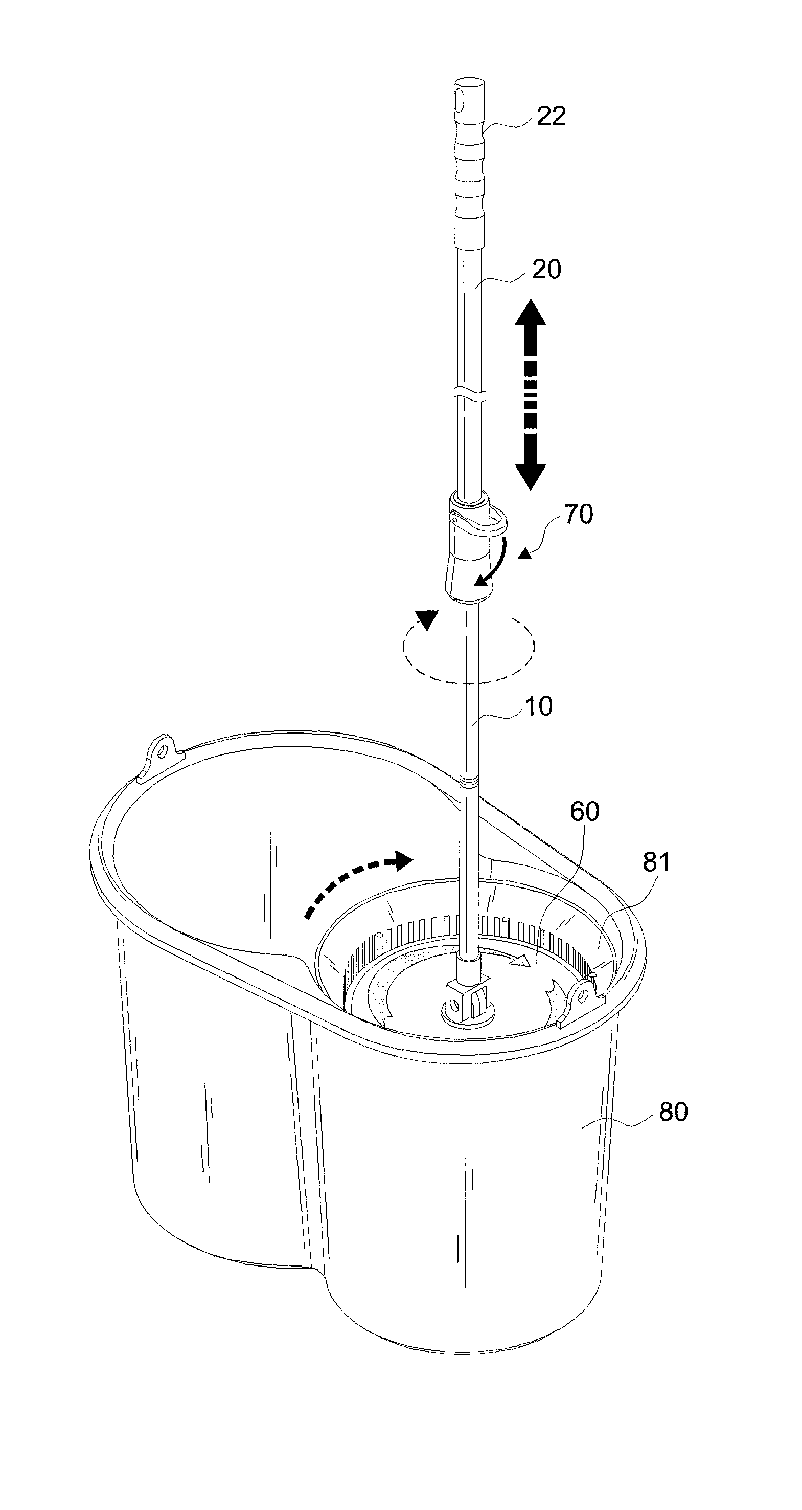
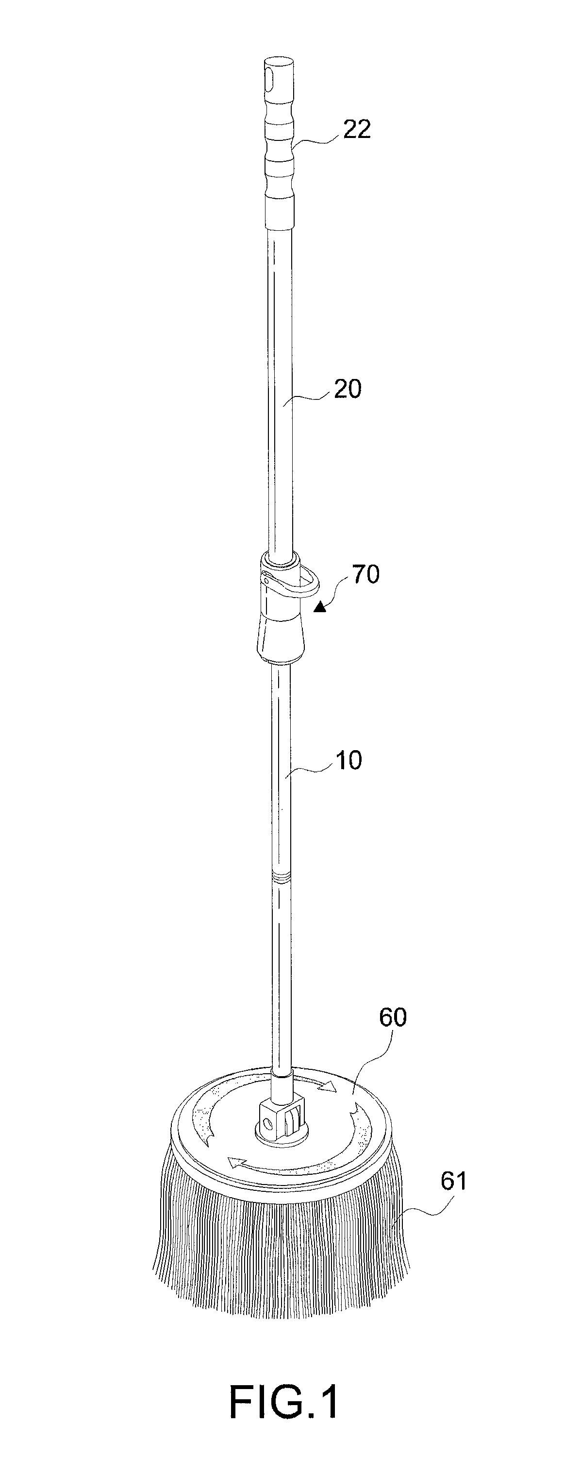
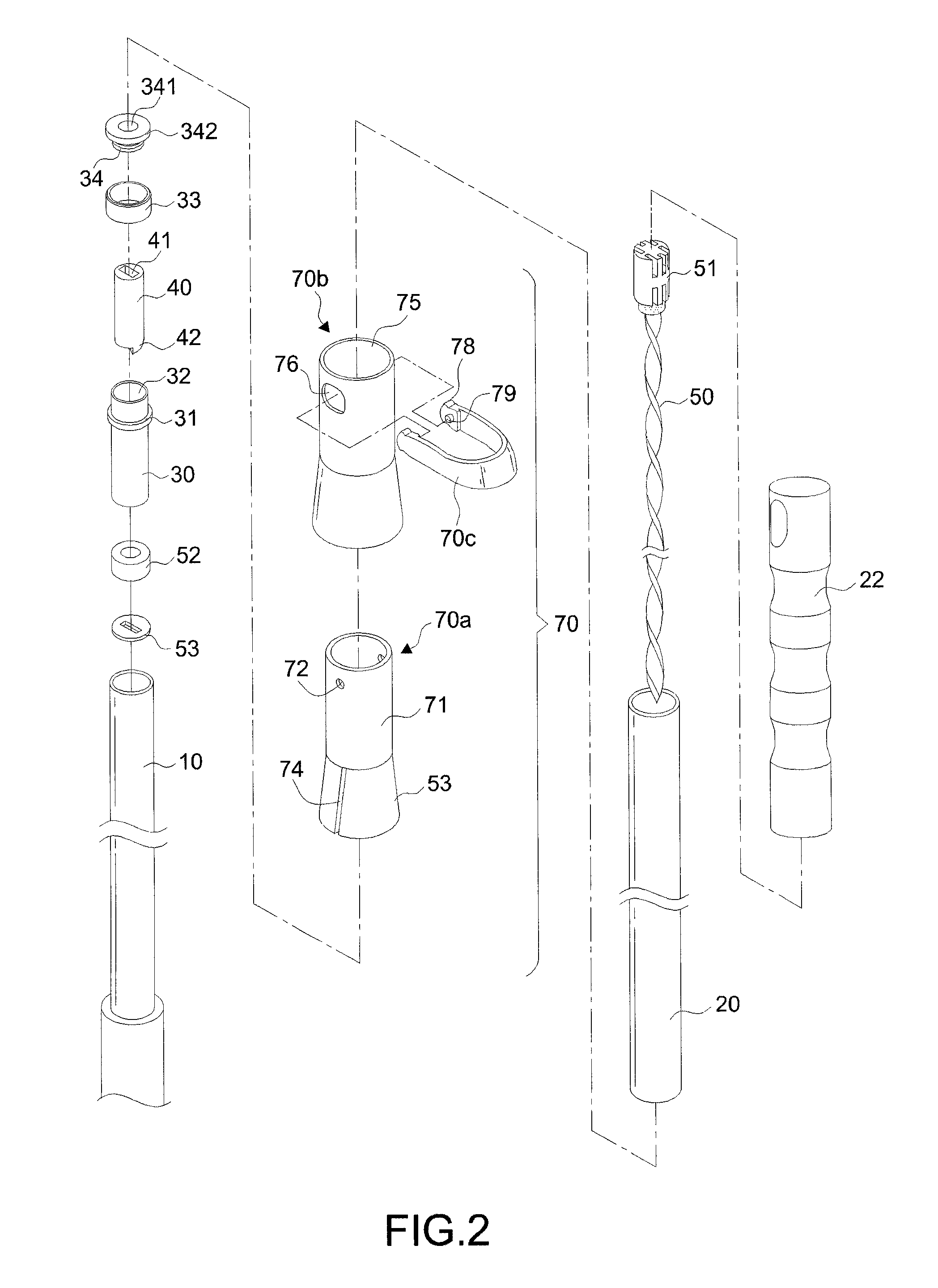
[0030]First of all, referring to FIGS. 1 through 8, a mop in accordance with the invention includes an internal rod 10, an external rod 20, an engaging element 30, a driving element 50, an actuating element 40, a disc body 60, and a locking mechanism 70.

[0031]The internal rod 10 is constructed as a hollow circular tube and made by metal or non-metal material. Therefore, it can be an aluminum tube or a plastic tube.

[0032]The external rod 20 includes a bottom portion in a telescopic connection with a top portion of the internal rod 10. According to the embodiment, the operator can hold on the external rod 20 to conduct a telescopic motion on the internal rod 10.

[0033]The engaging element 30 is positioned within the opening at the top of the internal rod 10. According to this embodiment, an annular element 33 and a fixing cap 34 are mounted and fixed on the engaging element 30 after the engaging element 30 is placed within the top of the internal rod 10. The upper portion of the engagi...


PUM

PropertyMeasurementUnit
external diameteraaaaaaaaaa
internal diameteraaaaaaaaaa
diameteraaaaaaaaaa

Abstract

A telescopically rotatable mop, comprising: an internal and external rod fitting to each other in a linearly and telescopically movable state; an engaging element positioned within the opening at the top of the internal rod; a driving element formed in an elongated shape and positioned within the external rod in such a way that the driving element is moved up and down synchronically with the external rod; an actuating element positioned within the engaging element for accommodating the driving element, the engaging element being driven in a single direction when the actuating element is rotated by the driving element. An annular element rotatable clockwise and counterclockwise at 360° is mounted on the top portion of the engaging element. The actuating element received within the engaging element has a smaller length, thereby creating a gap for the lifting and lowering purposes. In this way, a more smooth operation with less effort is ensured when the internal and external rods rotate in a telescopic way.

Description

BACKGROUND OF THE INVENTION[0001]1. Field of the Invention[0002]The invention relates to a telescopically rotatable mop, and more particularly to a structure that ensures a smooth operation in dewatering the mop with one hand only and without use of the feet.[0003]2. Description of the Related Art[0004]After a mop has been used, it is necessary to wring dirty water from mop fabrics (or cotton strips) of the mop before soaking clean water again to facilitate washing a floor, and mopping is obviously a tiresome job. Therefore, related manufacturers have developed various different dewatering devices for the mop, such as a dewatering device disclosed in R.O.C. Pat. No. 347146, wherein a pedal is provided for driving a gear to rotate a dewatering tank at a fast speed, so as to wring cotton strips of the mop placed in the dewatering tank. Although the aforementioned device can improve the inconvenient way of wringing the mop fabrics by hands, yet the operation still requires a user to st...

Claims


Application Information

Patent Timeline
Patent Type & Authority Patents(United States)
IPC IPC(8): A47L13/20A47L13/14
CPCA47L13/20A47L13/58B25G1/00
Inventor CHEN, YUNG-HUA
Owner TUO SHEN INT
Why Eureka
Try Eureka