Archery bow stabilizer

a stabilizer and archery technology, applied in the field of archery, can solve the problems of low hit rate, bow to be laterally and rotationally displaced, undesirably deflecting the arrow from its intended trajectory, etc., and achieve the effects of reducing side to side and up and down movement, reducing wobble and bow torque, and improving accuracy

Inactive Publication Date: 2012-07-17
MOGGO WILLIAM R
View PDF7 Cites 25 Cited by
  • Summary
  • Abstract
  • Description
  • Claims
  • Application Information

AI Technical Summary

Benefits of technology

[0020]The above-discussed disadvantages of the prior art are overcome by a bow stabilizer that includes a motor-driven gyroscope located inside a tube which is mounted on the bow. The stabilizer screws into front of bow where traditional stabilizer / vibration dampeners usually attach. The stabilizer of the present invention has an electric motor powered gyroscope. The stabilizer of the present invention removes wobble and bow torque when aiming. A force is created by the gyroscope spinning inside a tube and improves accuracy by reducing side to side and up and down movement during aiming. The stabilizer of the present invention also prevents torquing of the bow.

Problems solved by technology

Obviously, any tipping of the bow during release of the arrow undesirably deflects the arrow from its intended trajectory toward the target.
A further unavoidable occurrence following the archer's release of an arrow has been the tendency of the bow to be laterally and rotationally displaced, that is, the handle section of the bow moves in a vibrating manner in a direction away from the arrow as it passes around the bow handle.
Ill reaction of the main body tends to cause unstable flight of the arrow which results in low rate of hit.
In addition to bow torquing, archers are familiar with the fact that vibration and “bow kick” upon arrow release are frequently the cause of many inaccurate shots.
Vibration and bow kick are also physically discomforting to the archer engaged in frequent contests requiring many shots over a short period of time.
In addition, undesirable bow movement may tire the archer prematurely during sustained use.
This is undesirable in both target shooting and hunting.
Further, the vibration can create a noise which can be heard by game, which is undesirable during hunting.
Therefore, the system is underdamped.
Generally, the spring coefficient in this type of bow stabilizer is low, making the natural frequency of the stabilizer less than the natural frequency of the bow, and thus, the system is overdamped.
However, it is often difficult to tune the stabilizer for critical damping.
In addition, because the weights must be moveable to tune the stabilizer, the size of the weight is limited.
Thus, most tunable rod and mass configurations do not allow for enough damping material to adequately absorb the energy once it is captured by the stabilizer.

Method used


Image

  • Archery bow stabilizer
  • Archery bow stabilizer

Examples


Embodiment Construction

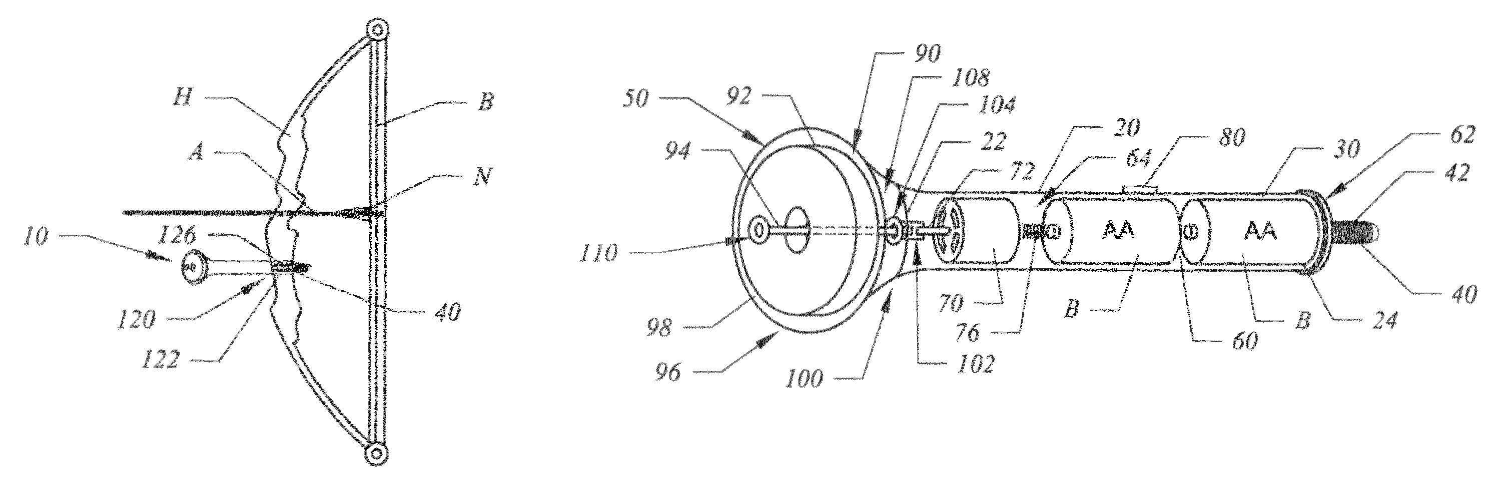
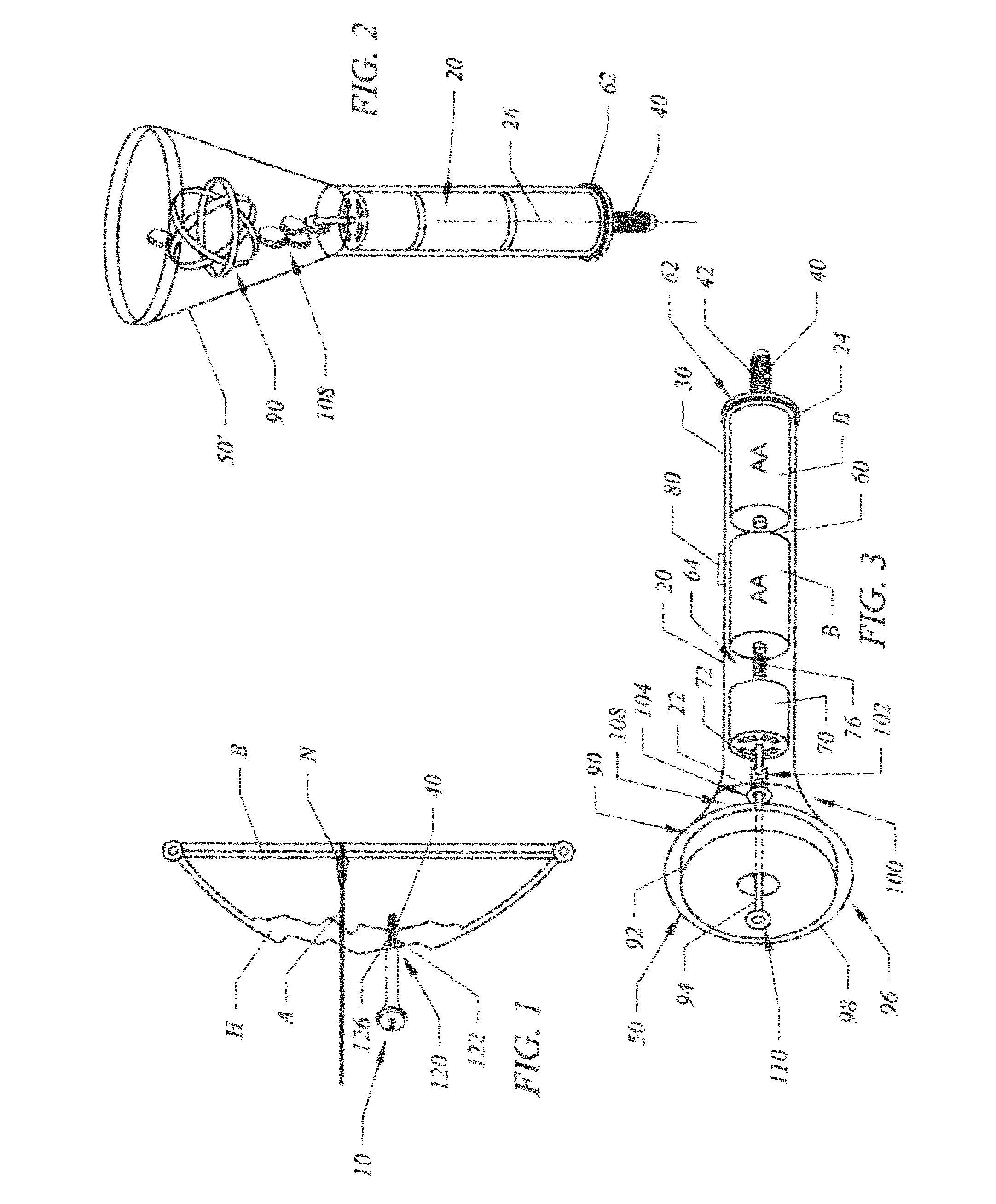
[0026]Referring to the figures, it can be understood that the present invention is embodied in a stabilizer unit 10 for use on an archery bow 12 to stabilize that bow. Stabilizer unit 10 comprises a main housing 20 having a first end 22, a second end 24 and a longitudinal axis 26 extending between the first end and the second end. Main housing 20 has a hollow interior 30.

[0027]A bolt 40 is located on the second end of the main housing and includes external screw threads 42. The main housing further includes a hollow portion 50 on the first end of thereof. The hollow portion is larger in external size than the main housing portion and can be spherical as shown in FIG. 2 or conical as shown at 50′ in FIG. 3. The shape of this portion allows it to be located in the most advantageous spot on the bow while transferring as much momentum as possible to the bow in a stabilizing manner.

[0028]A battery compartment 60 is located in the main housing to be adjacent to the second end of the main ...


PUM


Abstract

A stabilizer for an archery bow includes a motor-driven gyroscope located inside a tube which is mounted on the bow. The stabilizer screws into front of bow where traditional stabilizer/vibration dampeners usually attach. The stabilizer of the present invention has an electric motor powered gyroscope.

Description

TECHNICAL FIELD OF THE INVENTION[0001]The present invention relates to the general art of archery, and to the particular field of archery bow stabilizers.BACKGROUND OF THE INVENTION[0002]Recent years have seen an increased interest in the field of archery in general, and in target archery and hunting in particular. The accurate use of an archery bow is a skill which very nearly approaches an art form. It is generally considered to be considerably more difficult to shoot an archery bow accurately than a firearm, as the projectile (arrow) generally has a much higher percentage of mass in comparison to the bow than does a bullet to a gun, and the speed of the arrow is comparatively much less.[0003]An archery bow moves or vibrates in response to the forces generated upon release of the bow string from its drawn position to fire an arrow. According to well known principles of physics, as the string and arrow move toward the target, the bow tends to move in the opposite direction toward t...

Claims


Application Information

Patent Timeline
Patent Type & Authority Patents(United States)
IPC IPC(8): F41B5/20
CPCF41B5/1426F41G3/12
Inventor MOGGO, WILLIAM R.
Owner MOGGO WILLIAM R
Why Eureka
Try Eureka