Chronograph timepiece

A chronograph, precision technology, applied in the field of horology, which can solve the problems of unfavorable energy consumption, waste, etc.

Active Publication Date: 2009-04-29
OMEGA SA
View PDF1 Cites 2 Cited by
  • Summary
  • Abstract
  • Description
  • Claims
  • Application Information

AI Technical Summary

Problems solved by technology

However, it should be noted that this type of solution is disadvantageous from the point of view of energy consumption, because of the waste caused by friction

Method used


Image

  • Chronograph timepiece
  • Chronograph timepiece

Examples


Embodiment Construction

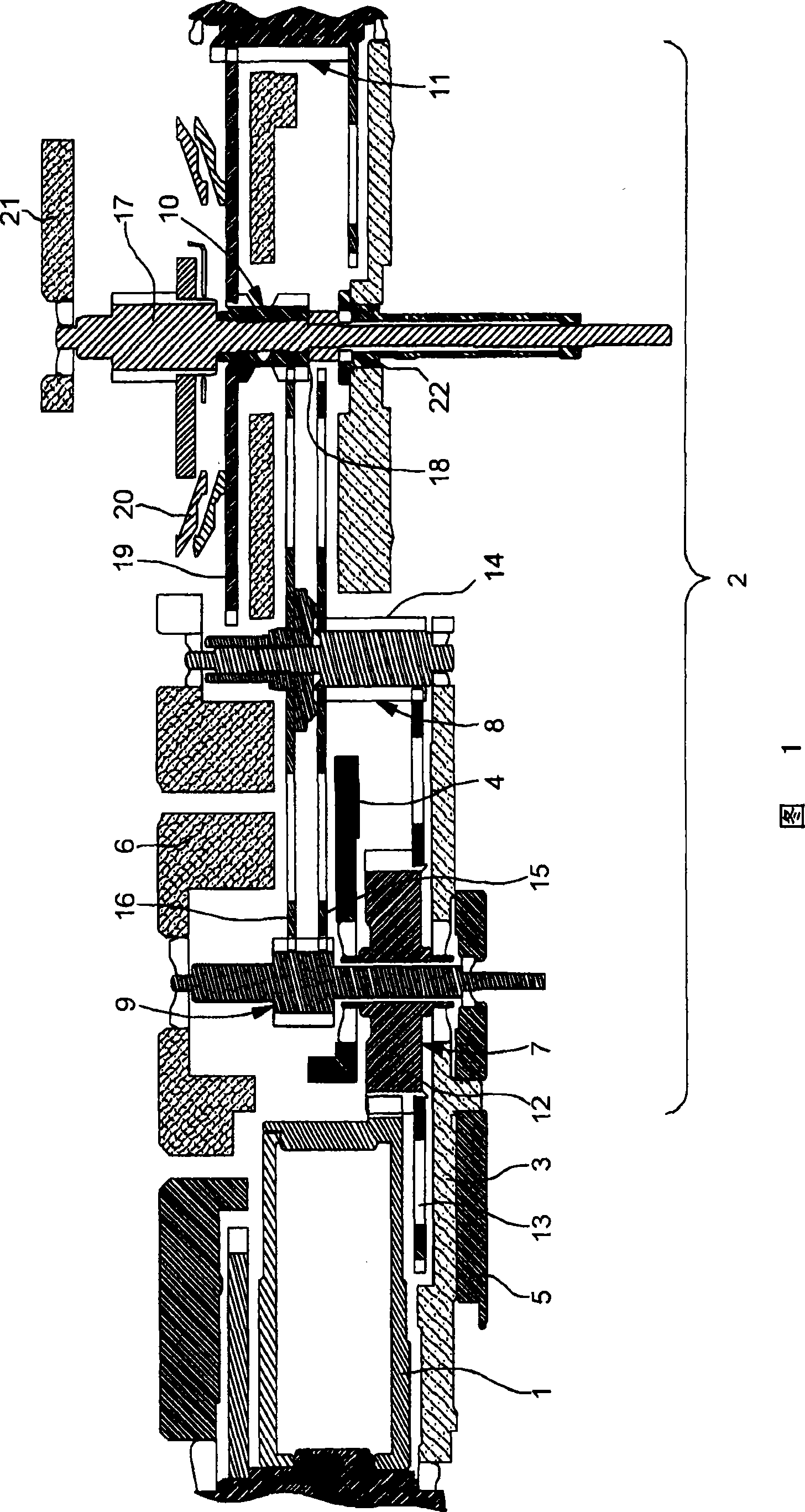
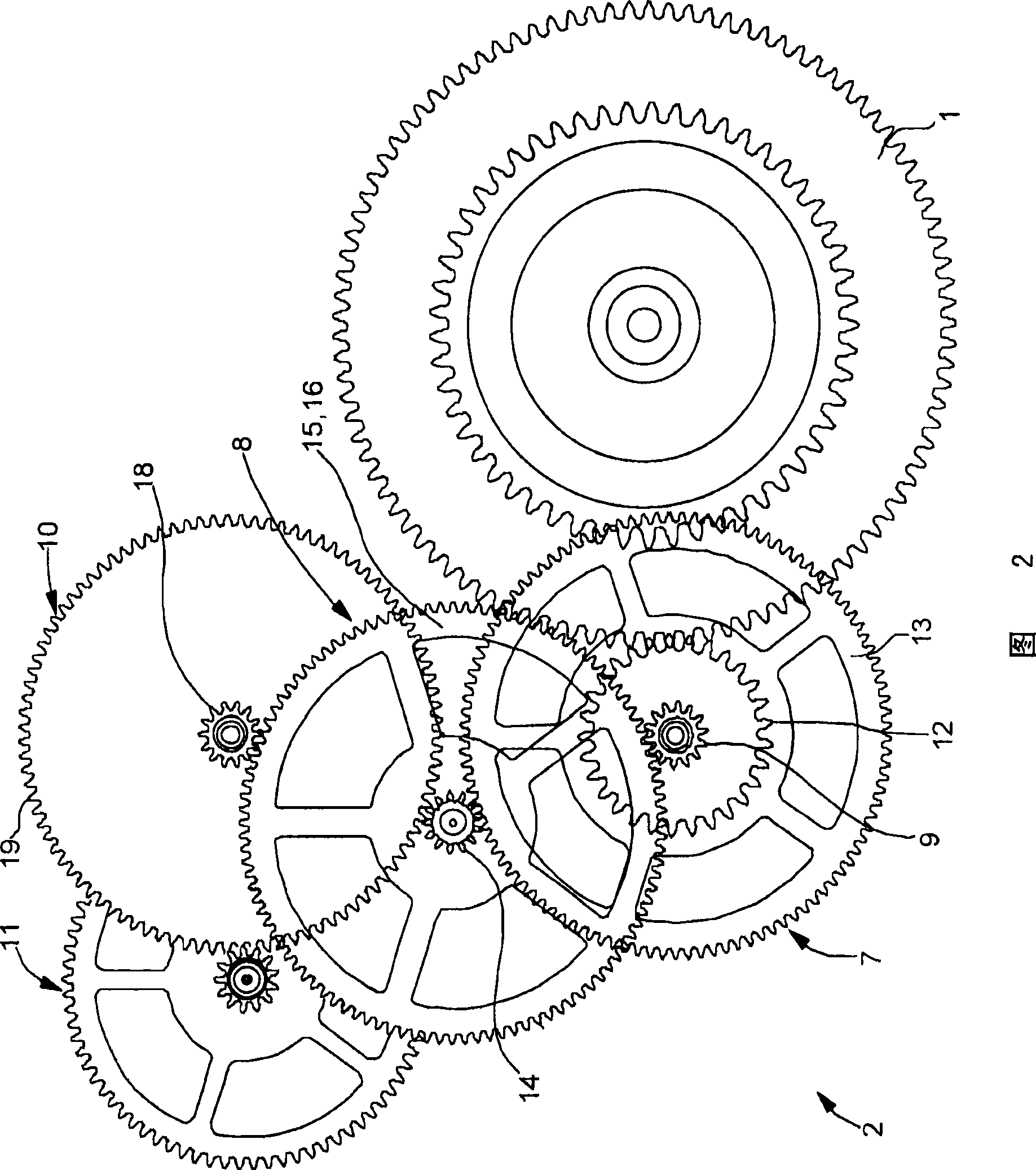
[0013] The chronograph shown in Figures 1 and 2 comprises: an energy accumulator element in general, a barrel 1, and a running wheel train 2 for transferring energy from barrel 1 to a distribution element (not shown). This assembly is installed between the plate 3 , the central wheel set bridge 4 , the fixed seconds bridge 5 and the gear train bridge 6 . The running train 2 comprises a central wheel set 7 mounted in series from the barrel 1, a third wheel set 8, an eccentric fixed seconds wheel set 9 secured in rotation to a fixed seconds display element not shown in the figure, a central precision seconds Wheel set 10 and middle escape wheel set 11.

[0014] The center wheel set 7 is composed of a center pinion 12 meshing with the barrel 1 and a center wheel 13 fastened in rotation to the center pinion 12 . The center wheel set is installed between the flat plate 3 and the third wheel bridge 4 . The center wheel 13 drives in rotation a third wheel set 8 mounted between the ...


PUM


Abstract

The present invention concerns a chronograph watch fitted with a going train including: a permanent seconds wheel set secured to a permanent seconds display member, a chronograph seconds wheel set cooperating with a coupling in order to be secured to a chronograph seconds display member, and a third wheel set including a first third wheel fixedly mounted in rotation, meshed either with the permanent seconds wheel set, or with the chronograph seconds wheel set. The going train further includes a second third wheel mounted to move freely, meshed on the one hand, with the permanent seconds wheel set, and on the other hand, with the chronograph seconds wheel set.

Description

technical field [0001] The invention relates to the field of horology. More particularly, the invention relates to a chronograph equipped with a permanent seconds counter and a precision seconds counter. Background technique [0002] A chronograph of this type generally comprises a running wheel train forming the energy transmission chain from the energy accumulator element, the barrel to the energy distributor element, the escapement. This running train usually consists of a center wheel set, a third wheel set and a precision seconds wheel set mounted in series between the barrel and the escapement. The running train further comprises a fixed seconds wheel mounted in parallel with this third wheel set, fastened to the fixed seconds display element. Mounted in this way, the fixed second wheel set is positioned at the end of the gear train consisting of the center wheel set, the third wheel set and the fixed second wheel set. [0003] Because the fixed seconds wheel set is...

Claims


Application Information

Patent Timeline
Patent Type & Authority Applications(China)
IPC IPC(8): G04B19/02G04B13/00G04B35/00G04F7/08
CPCG04F7/08G04B35/00G04F7/0866G04F7/00
Inventor B·罗宾
Owner OMEGA SA
Why Eureka
Try Eureka