Power transmission mechanism

a transmission mechanism and power technology, applied in the direction of fluid gearings, couplings, belts/chains/gearrings, etc., can solve the problems of promoting wear and affecting driving behavior, and achieve the effects of reducing wear, reducing wear, and reducing wear

Inactive Publication Date: 2012-07-17
SCHAEFFLER TECH AG & CO KG
View PDF28 Cites 2 Cited by
  • Summary
  • Abstract
  • Description
  • Claims
  • Application Information

AI Technical Summary

Benefits of technology

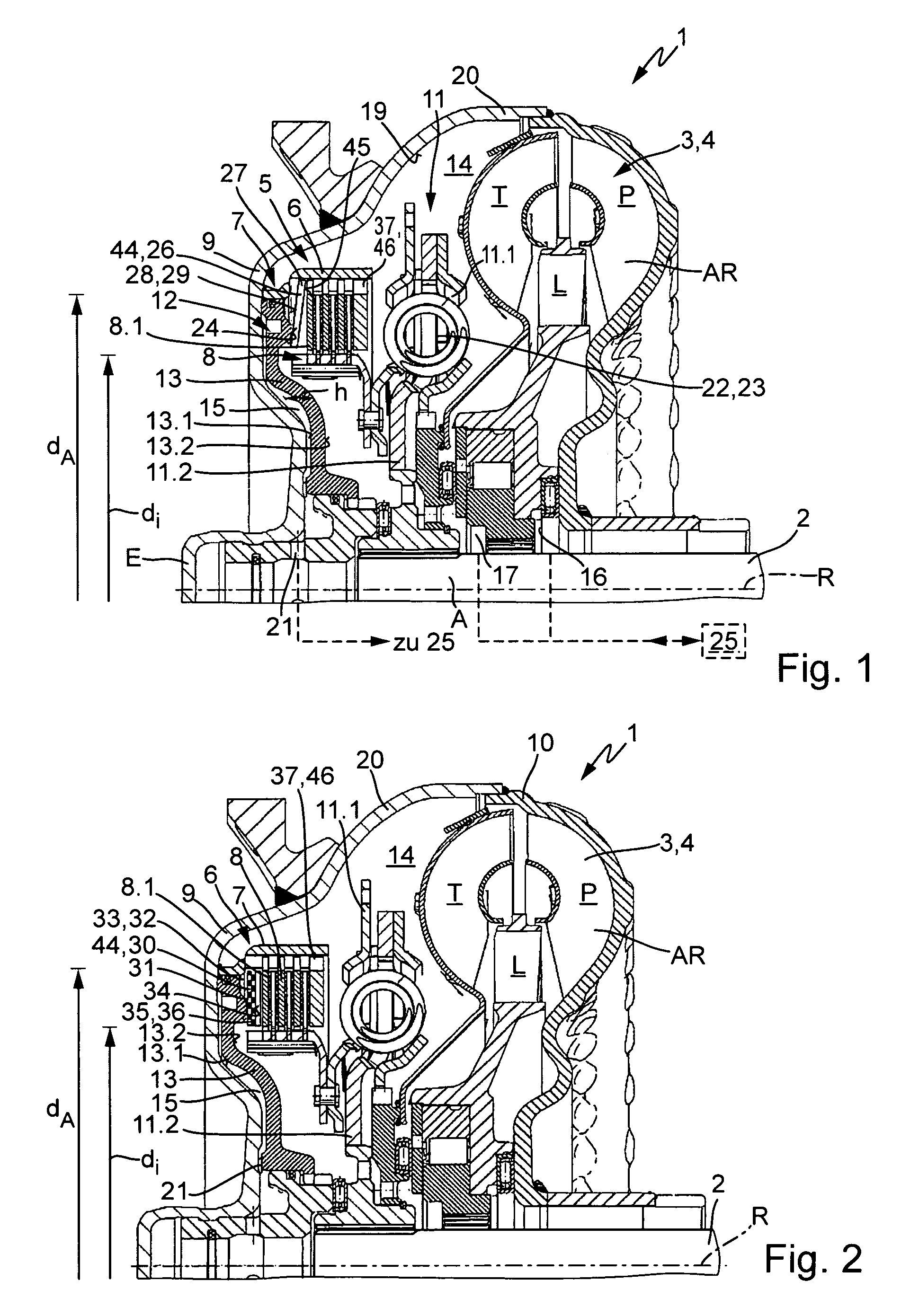
[0011]Interposing elastic elements makes it possible to compensate in a simple manner for a momentary strong pressure rise while at the same time improving the feeling of the switching for the operator of such power transmission mechanisms, in particular in vehicles. The elastic element can be designed and constructed so that it is characterized by different elasticity characteristics in different directions, whereby properties may be produced that differ in their directional dependency. In particular, great stiffness is demanded in the circumferential direction and great elasticity, in particular a high modulus of elasticity, in the axial direction.
[0012]According to an especially advantageous embodiment, spring elements are employed as elastic elements. These are used to achieve a uniform distribution of force in the circumferential direction, preferably situated coaxially to the actuating mechanism and clutch device. Because of the properties of spring units, the spring unit enables the buildup of a force parallel to or proportional to the path on the device, to at least partially bridge over the hydrodynamic component. That mitigates or smoothes the transition from path control to power control, and the engagement impact can be reduced.
[0015]The first embodiment enables simple integration, and thereby retrofitting from switchable clutch devices to the clutch device with a spring unit according to the invention. The second embodiment, when executed appropriately with concentration of the functions of stop and elastic element, enables especially space-saving construction in the axial direction. A further advantage of the placement of the spring units between the plate pack and the stop element consists in the fact that as the clutch torque becomes greater, the friction of displacement and thus the damping of the engagement impact are also increased.
[0019]There is a plurality of possibilities for the spring unit to be used. In the simplest cases it is formed by at least one diaphragm spring, with the inner diameter and the outer diameter of the diaphragm spring being chosen so that they are situated in the area of the radial extension of the elements of the clutch parts that form the frictional surfaces, and also cannot extend beyond it in the tensioned state, so that flat contact can be realized over the diaphragm springs, at least in partial areas. A significant advantage of using a diaphragm spring consists in the improved distribution of surface pressure.
[0023]An object of the invention is to further develop a power transmission mechanism of the type named at the beginning, in particular having a hydrodynamic component and a device for at least partially bridging over the latter, in such a way that the engagement impact is largely prevented, or at least the transition between the path-controlled and the power-controlled operating modes is substantially softer, by lessening the pressure increase.

Problems solved by technology

However, that is normally accompanied by a strong engagement impact, which is caused in part by the non-equilibrium of the centrifugal oil pressures on the piston element of the control device for the lockup clutch.
A disadvantage of the systems known heretofore is in particular the engagement impact, which has a negative impact on the driving behavior and also promotes wear.

Method used


Image

  • Power transmission mechanism
  • Power transmission mechanism
  • Power transmission mechanism

Examples


Embodiment Construction

[0033]At the outset, it should be appreciated that like drawing numbers on different drawing views identify identical, or functionally similar, structural elements of the invention. While the present invention is described with respect to what is presently considered to be the preferred aspects, it is to be understood that the invention as claimed is not limited to the disclosed aspects.

[0034]Furthermore, it is understood that this invention is not limited to the particular methodology, materials and modifications described and as such may, of course, vary. It is also understood that the terminology used herein is for the purpose of describing particular aspects only, and is not intended to limit the scope of the present invention, which is limited only by the appended claims.

[0035]Unless defined otherwise, all technical and scientific terms used herein have the same meaning as commonly understood to one of ordinary skill in the art to which this invention belongs. Although any meth...


PUM


Abstract

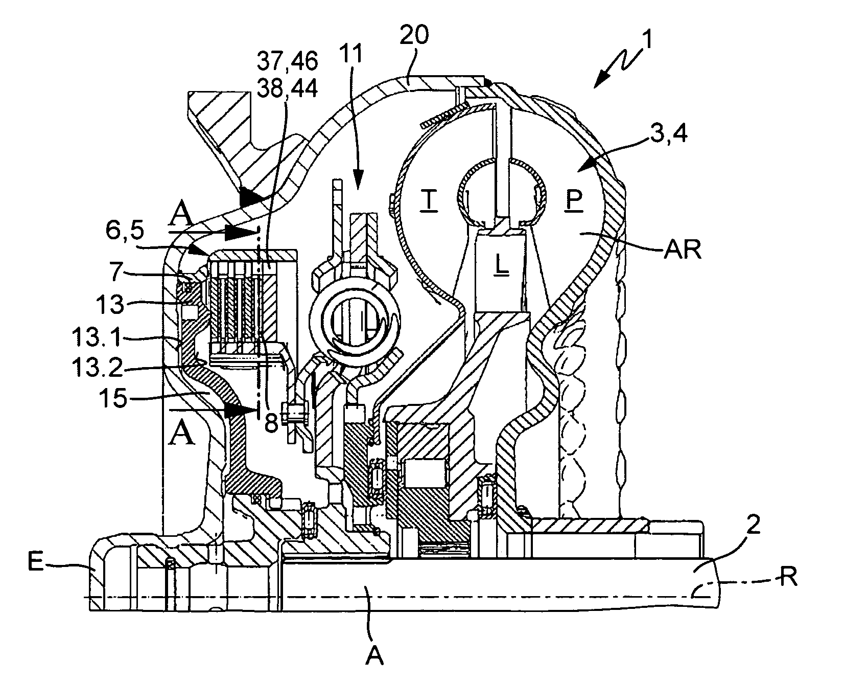
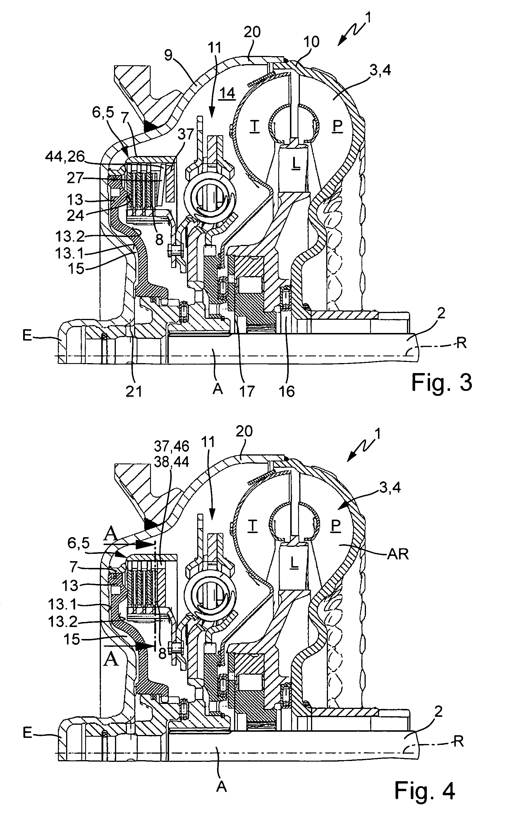
A power transmission mechanism including at least one hydrodynamic component and a device for at least partially bridging over the transmission of power through the hydrodynamic component by means of a control device, having an actuating mechanism that can be charged by way of a chamber that is chargeable with a pressurizing agent, and at least one spring unit is interposed between the actuating mechanism and the device for at least partially bridging over the hydrodynamic component.

Description

CROSS-REFERENCE TO RELATED APPLICATIONS[0001]This patent application claims priority from German Patent Application No. 10 2007 054 584.5, filed Nov. 15, 2007, which application is incorporated herein by reference.FIELD OF THE INVENTION[0002]The invention relates to a power transmission mechanism, comprising at least one input and one output, a hydrodynamic component and a device for at least partially bridging over the transmission of power through the hydrodynamic component with a control device (12) assigned to the latter, comprising an actuating mechanism (13) that is actuatable by means of a chamber (15) that can be charged with a pressurizing agent.BACKGROUND OF THE INVENTION[0003]Power transmission mechanisms that can be implemented between a drive machine and a gear component in drive trains, particularly for mobile applications, and even more particularly for motor vehicles, are known in a multitude of versions from the existing art. These generally comprise an input and at...

Claims


Application Information

Patent Timeline
Patent Type & Authority Patents(United States)
IPC IPC(8): F16H45/02
CPCF16H45/02F16H2045/021F16H2045/0247F16H2045/0284
Inventor KRAUSE, THORSTENDANIEL, BENJAMIN
Owner SCHAEFFLER TECH AG & CO KG
Why Eureka
Try Eureka