Rolling-lobe air spring having a drop base ring clamp contour

Active Publication Date: 2012-07-17
CONTITECH LUFTFEDERSYST
View PDF9 Cites 11 Cited by
  • Summary
  • Abstract
  • Description
  • Claims
  • Application Information

AI Technical Summary

Benefits of technology

[0006]The task of the present invention is therefore a reliable attachment of a sleeve rolling-lobe flexible member to a connecting part.

Problems solved by technology

In view of the fact that the flexible member is provided with a reinforcement, which is expandable slightly compared to the rubber, the problem is present that the considerable longitudinal displacement of the elastomeric material can lead to unwanted excessive longitudinal stresses within the flexible member and therefore to a possible separation of the elastomeric material from the rein

Method used


Image

  • Rolling-lobe air spring having a drop base ring clamp contour
  • Rolling-lobe air spring having a drop base ring clamp contour
  • Rolling-lobe air spring having a drop base ring clamp contour

Examples


Example

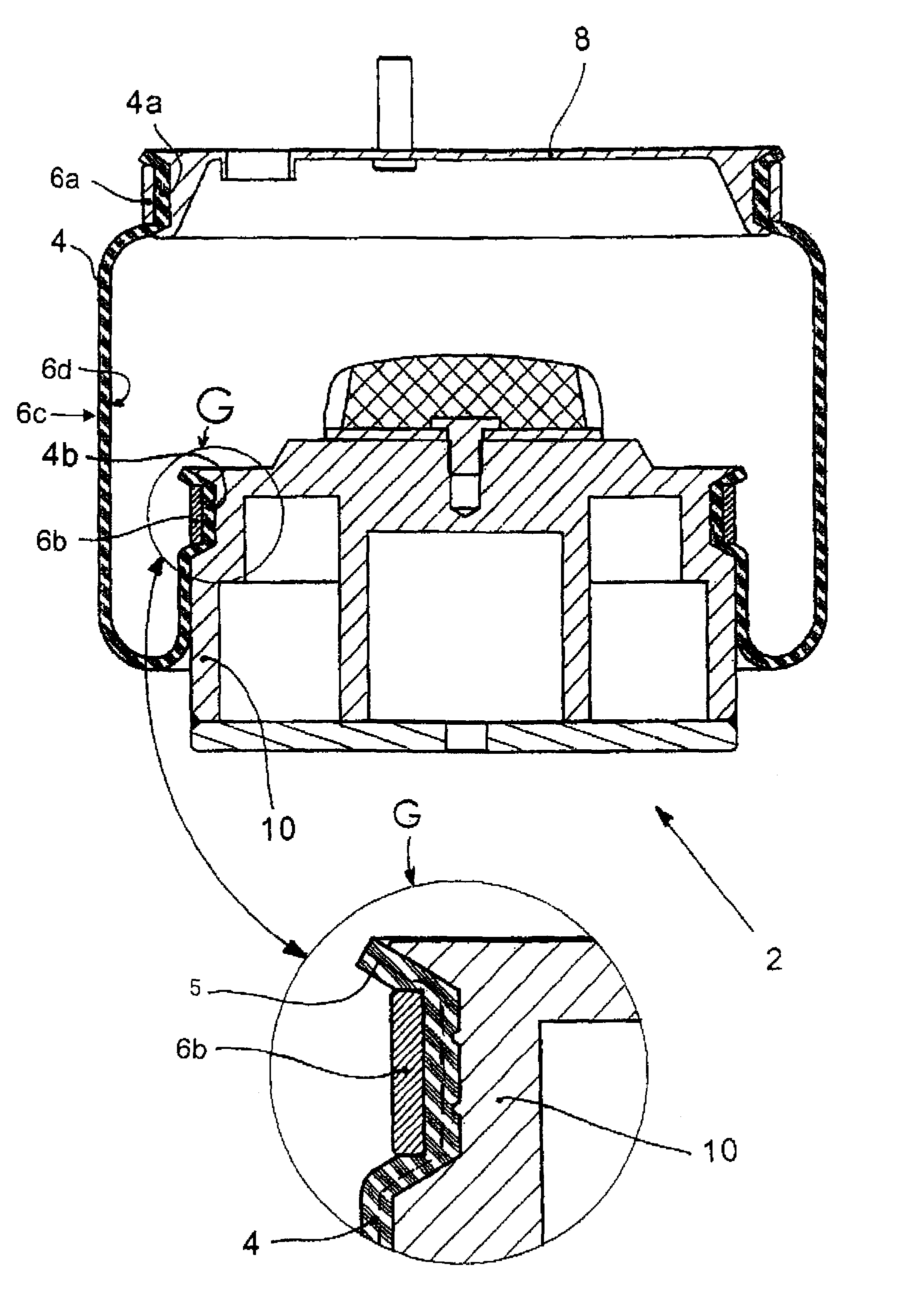
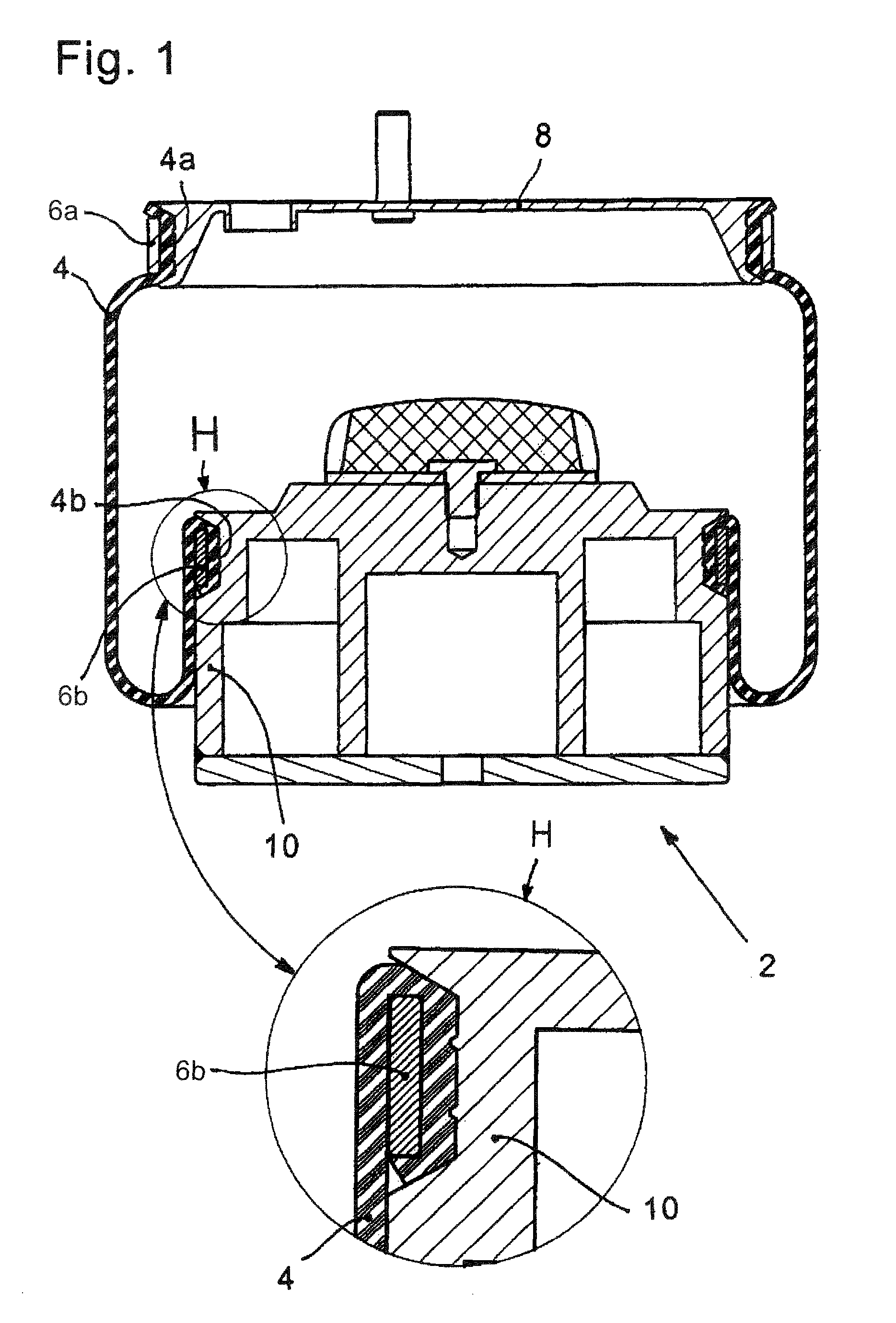
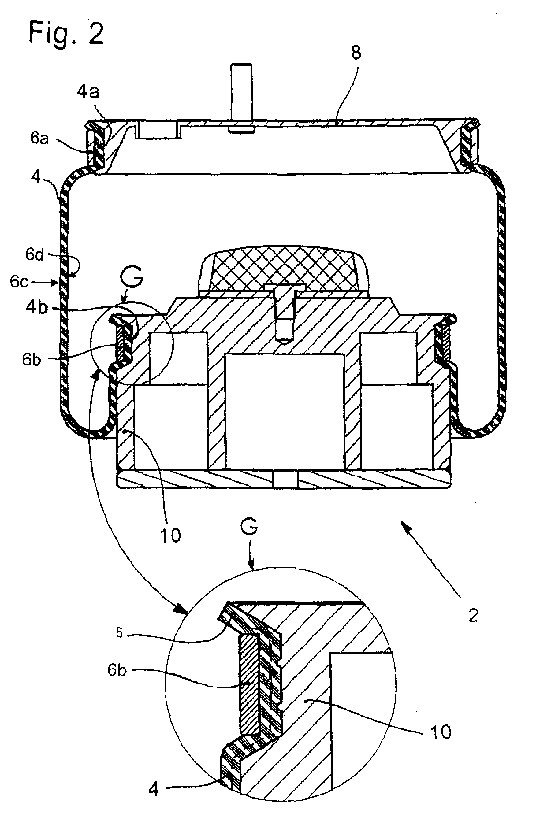
[0023]The air springs 2 shown in FIGS. 1 and 2 comprise essentially a sleeve rolling-lobe flexible member 4 having end sections (4a, 4b) which are applied form tight, pull tight and pressure tight to respective connecting parts (8, 10). As shown in FIG. 2, reinforcement 5 is integrated into the sleeve rolling-lobe flexible member 4. The upper connecting part 8 is, in each case, an air spring cover while the lower connecting part 10 is, in each case, a roll-off piston. Each of the connecting parts (8, 10) has a specially formed slot 12 for attaching corresponding ends (4a, 4b) of the sleeve rolling-lobe flexible member. End section 4a or 4b of a sleeve rolling-lobe member 4 is placed in corresponding slots 12 and clamped with the aid of a corresponding clamp ring (6a, 6b). Because of the plastic deformation of the clamp ring (6a, 6b), the sleeve rolling-lobe flexible member 4 is pressed into the slot 12 which extends peripherally around each connecting part 8 and / or 10 and is configu...


PUM


Abstract

A flexible member air spring has an end section of the flexible member attached to a connecting part by a clamp ring. The connecting part has a slot having a truncated cone-shaped cross section. The base of the slot is cylindrical and a flank of the slot has a linear conical form. The inner surface of the clamp ring extends parallel to the base surface. In the clamped state, the inner radius of the clamp ring is less than or equal to at least one of the radii of the slot upper edges. The flexible member is not compressed between the base surface of the slot and the inner side of the clamp ring. The clamp ring, with at least one slot flank, forms a constriction clamping the flexible member wall of the end section.

Description

RELATED APPLICATION[0001]This application is the national stage of PCT / EP 2005 / 010789, filed Oct. 7, 2005, designating the United States and claiming priority from German patent application no. 10 2004 056 517.1, filed Nov. 24, 2004, the entire contents of which are incorporated herein by reference.FIELD OF THE INVENTION[0002]The invention relates to a rolling-lobe air spring and especially the attachment of a rolling-lobe flexible member to a connecting part (air spring cover and / or roll-off piston). The connecting part is to be applied pressure tight at the ends to the flexible member with each end being form tight and pull tight.BACKGROUND OF THE INVENTION[0003]U.S. Pat. No. 5,005,808 is directed to the end attachment of an air spring flexible member to respective connecting parts. FIG. 4 shows all essential details. The attachment part includes a slot for attaching a sleeve rolling-lobe flexible member end section. This slot has a base surface which can be provided with peripher...

Claims


Application Information

Patent Timeline
IPC IPC(8): F16F9/04
CPCF16F9/0463
Inventor BANK, CHRISTOPHCERNY, PAULGAWINSKI, HUBERTUS
Owner CONTITECH LUFTFEDERSYST
Why Eureka
Try Eureka