
Method of processing reply cards

a reply card and card processing technology, applied in the field of mail handling, can solve the problems of high processing cost, difficult to achieve large-scale solutions, and constraints

Inactive Publication Date: 2012-07-17
NEOPOST TECH SA
View PDF11 Cites 2 Cited by
  • Summary
  • Abstract
  • Description
  • Claims
  • Application Information

AI Technical Summary

Benefits of technology

"The present invention provides a method for processing a reply card returned by its recipient, which method involves using a radio-frequency analysis device to determine if the reply card has been tampered with. The method includes analyzing the position of conductive signs printed on the reply card to determine if the recipient has taken any physical action on the card. This analysis can be done by a radio-frequency read device that is simple and low-cost. The invention also provides a reply card that allows the recipient to answer requests made by the sender by taking physical action on the card, such as detaching a portion of the conductive signs printed on the card. The unique identification code printed on the card can be used to recognize the recipient and is associated with a database of recipient addresses. The invention also provides a module for processing reply cards in a mail-handling machine, which module includes a radio-frequency analysis device for analyzing the conductive signs on the card."

Problems solved by technology

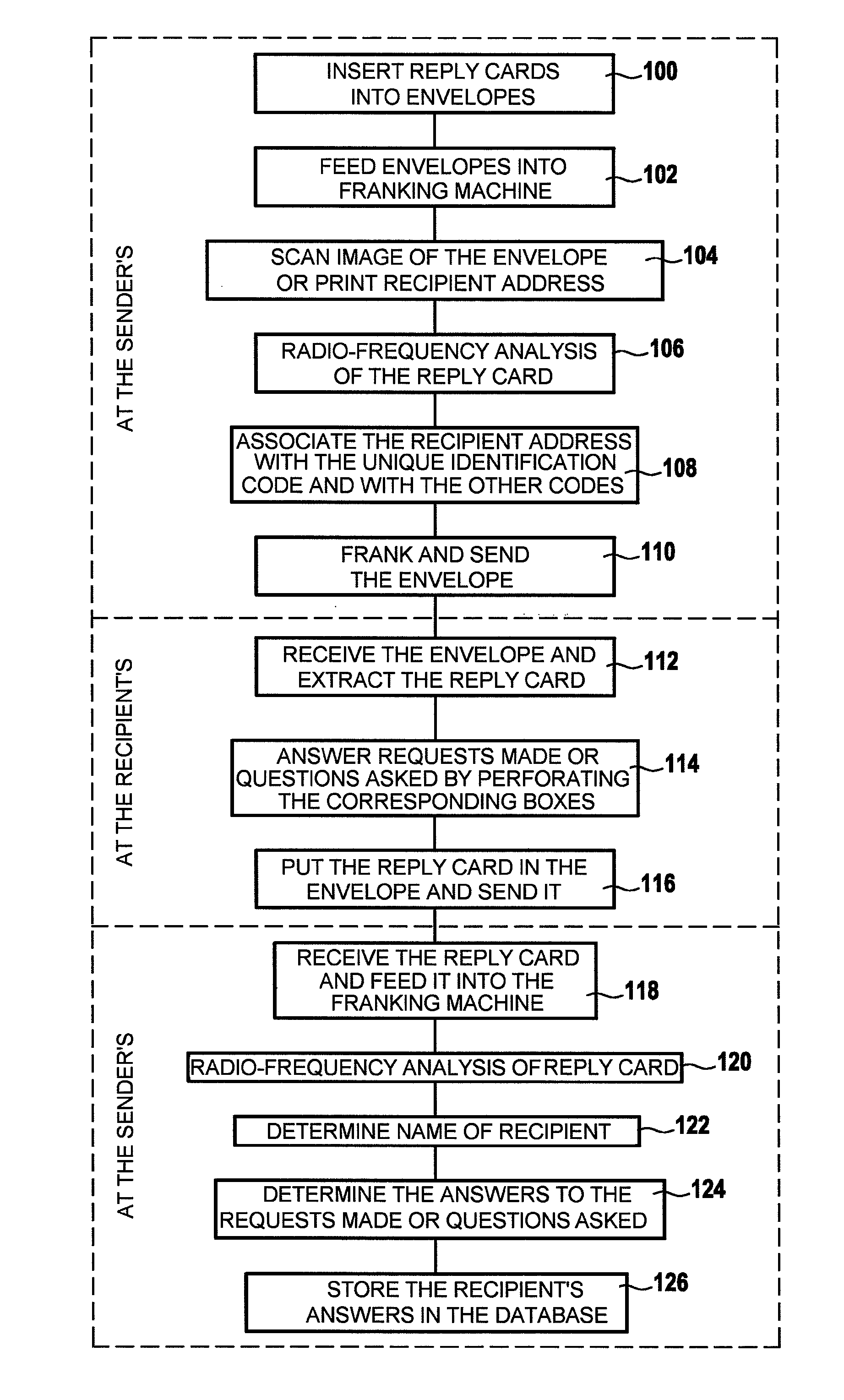
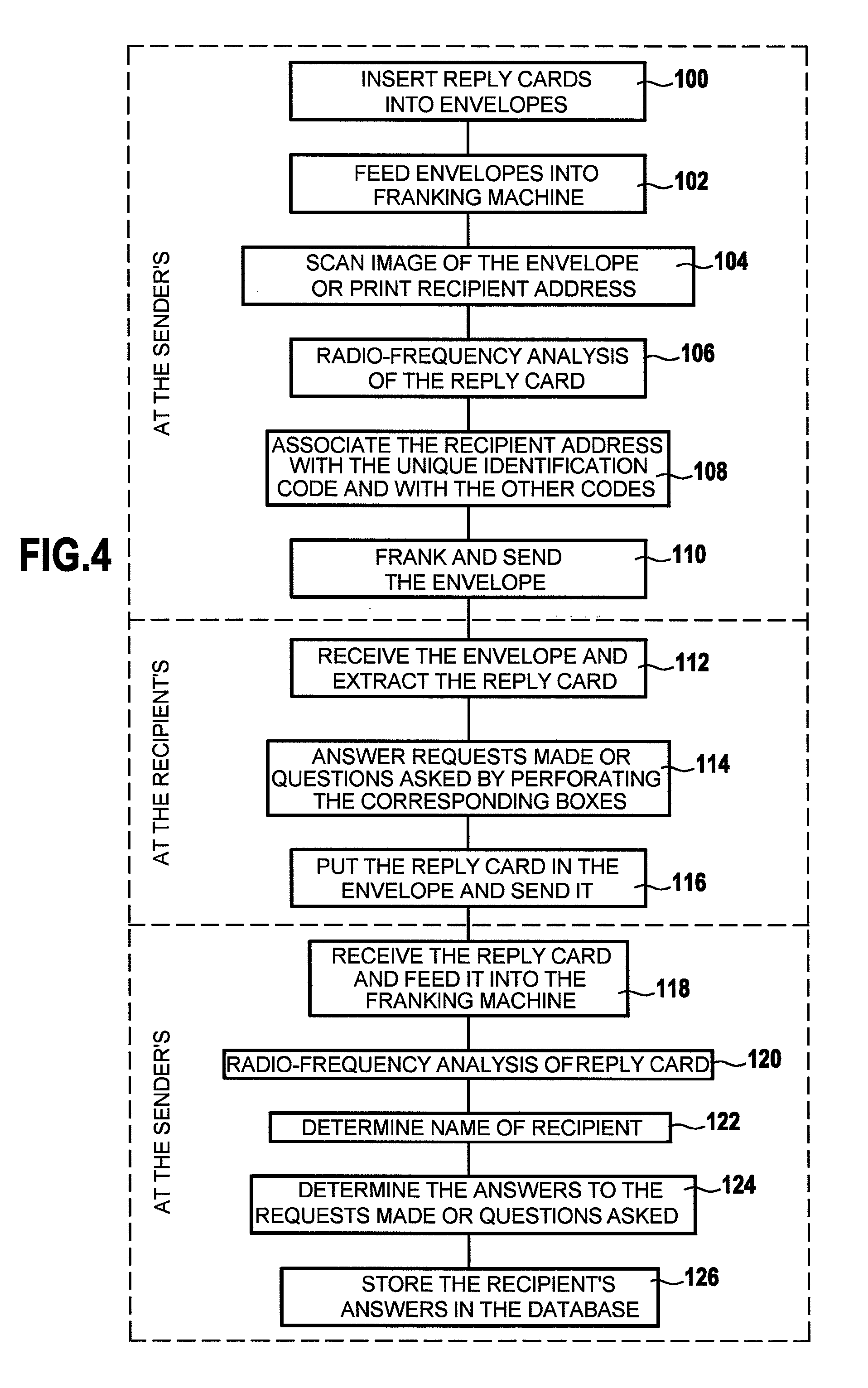
Such processing is costly because either it is performed manually and therefore requires major human resources, or else it is automated and therefore requires suitable technical means for opening the envelopes, extracting the reply cards, and reading the information put on the reply cards.
Unfortunately, such a solution can hardly be entertained on a large scale because it presupposes that each potential recipient has an RFID reader / recorder available at home, which is not so currently.
There therefore exists a need that is currently unsatisfied for a method of processing such reply cards that makes it possible to limit the costs of processing by the sender while also limiting the constraints imposed upon the recipient.

Method used


Image

  • Method of processing reply cards
  • Method of processing reply cards
  • Method of processing reply cards

Examples


Embodiment Construction

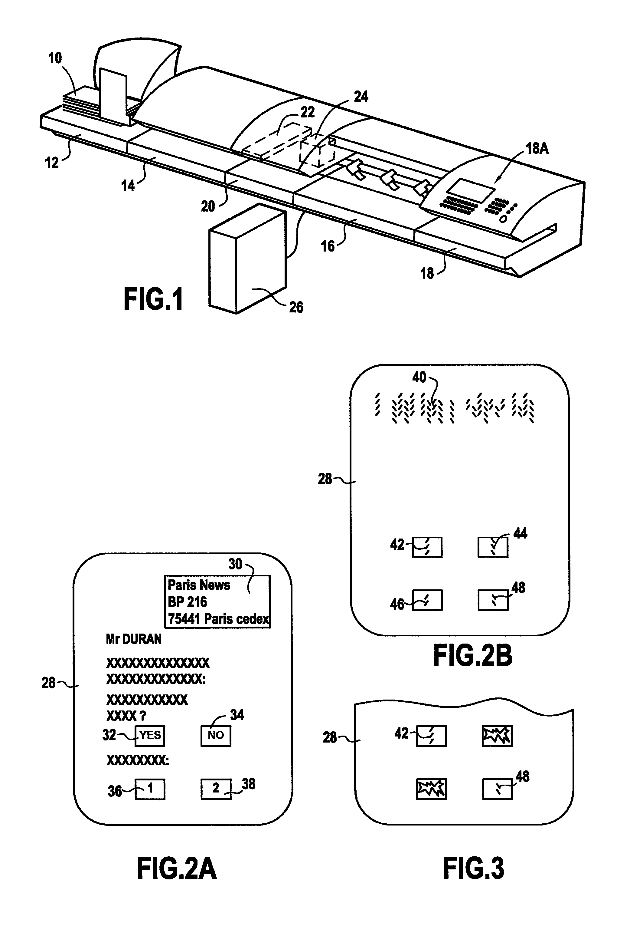
[0022]FIG. 1 shows an example of a mail-handling machine that, as is known and disposed going from upstream to downstream in the direction in which the mailpieces 10 advance, comprises: a mailpiece feed module 12 designed to receive a stack of mailpieces that are typically constituted by mixed mail (i.e. mailpieces of different sizes and weights); a selector and conveyor module 14 for selecting and conveying the mailpieces one-by-one; preferably a dynamic weigh module 16 (dynamic scales) for determining the weight and optionally the size of each selected mailpiece; and a print module 18 designed to print a postal imprint on each of the mailpieces selected one-by-one in this manner. The print module is preferably, as is also known, connected to a server (not shown) of a dealer of the machine, itself also connected to a server (not shown) of a postal authority or of a private carrier delivering the mail. The mailpieces that are franked are then ejected into an unloading tray (or a mai...


PUM


Abstract

In a reply card enabling a recipient of said reply card to answer at least one request made by a sender of said reply card by taking a determined physical action on at least one identified zone of said reply card, provision is made for at least one identified zone of said reply card to be provided with a succession of signs printed with a conductive ink, and for a determined physical action to be taken that consists in perforating at least one of said identified zones so as to detach at least a portion of said succession of signs printed with a conductive ink from the reply card, the effect of said detaching being to prevent a radio-frequency read device possessed by the sender from receiving the answer associated with said succession of signs printed with a conductive ink and detached by the recipient.

Description

TECHNICAL FIELD[0001]The present invention relates exclusively to the field of mail handling, and it relates more particularly to a method of processing reply cards, and to the associated reply cards.PRIOR ART[0002]Even nowadays, despite the rapid development of electronic commerce or “e-commerce” since the advent of the Internet, retailers and other traders still send their customers and prospective customers or “prospects” mail including reply cards for returning after answering the sender's questions or requests by marking various boxes present on the reply cards.[0003]Processing such a reply card requires the sender to perform various operations, namely opening the envelope containing the reply card, extracting the card, and reading the information put on it by the recipient so as to match up that information with the sender's relevant data relating to the sending of the reply cards. Such processing is costly because either it is performed manually and therefore requires major h...

Claims


Application Information

Patent Timeline
Patent Type & Authority Patents(United States)
IPC IPC(8): B42D1/00B42D19/00B42D15/00
CPCG07B17/00508G07B2017/00629G07B2017/00653
Inventor CHATTE, FABIEN
Owner NEOPOST TECH SA
Learn More