Method for making thermal interface material

a technology of thermal interface material and thermal interface material, which is applied in the direction of manufacturing tools, semiconductor/solid-state device details, other domestic articles, etc., can solve the problems of limited performance of thermal interface material and the heat conduction coefficient of thermal interface material is now considered too low for many contemporary applications

Active Publication Date: 2012-07-17
TSINGHUA UNIV +1
View PDF29 Cites 15 Cited by
  • Summary
  • Abstract
  • Description
  • Claims
  • Application Information

AI Technical Summary

Benefits of technology

[0008]What is needed, therefore, is to provide a method for making a thermal interface material with a high heat conduction coefficient.

Problems solved by technology

However, the performance of the thermal interface material is restricted by a heat conduction coefficient thereof.
Heat conduction coefficients of thermal interface materials are now considered to be too low for many contemporary applications.
Mechanical stresses are induced during temperature cycling and tend to overstress the electronic component, which can potentially leads to failures.

Method used


Image

  • Method for making thermal interface material
  • Method for making thermal interface material
  • Method for making thermal interface material

Examples


Embodiment Construction

[0014]The disclosure is illustrated by way of example and not by way of limitation in the figures of the accompanying drawings in which like references indicate similar elements. It should be noted that references to “an” or “one” embodiment in this disclosure are not necessarily to the same embodiment, and such references mean at least one.

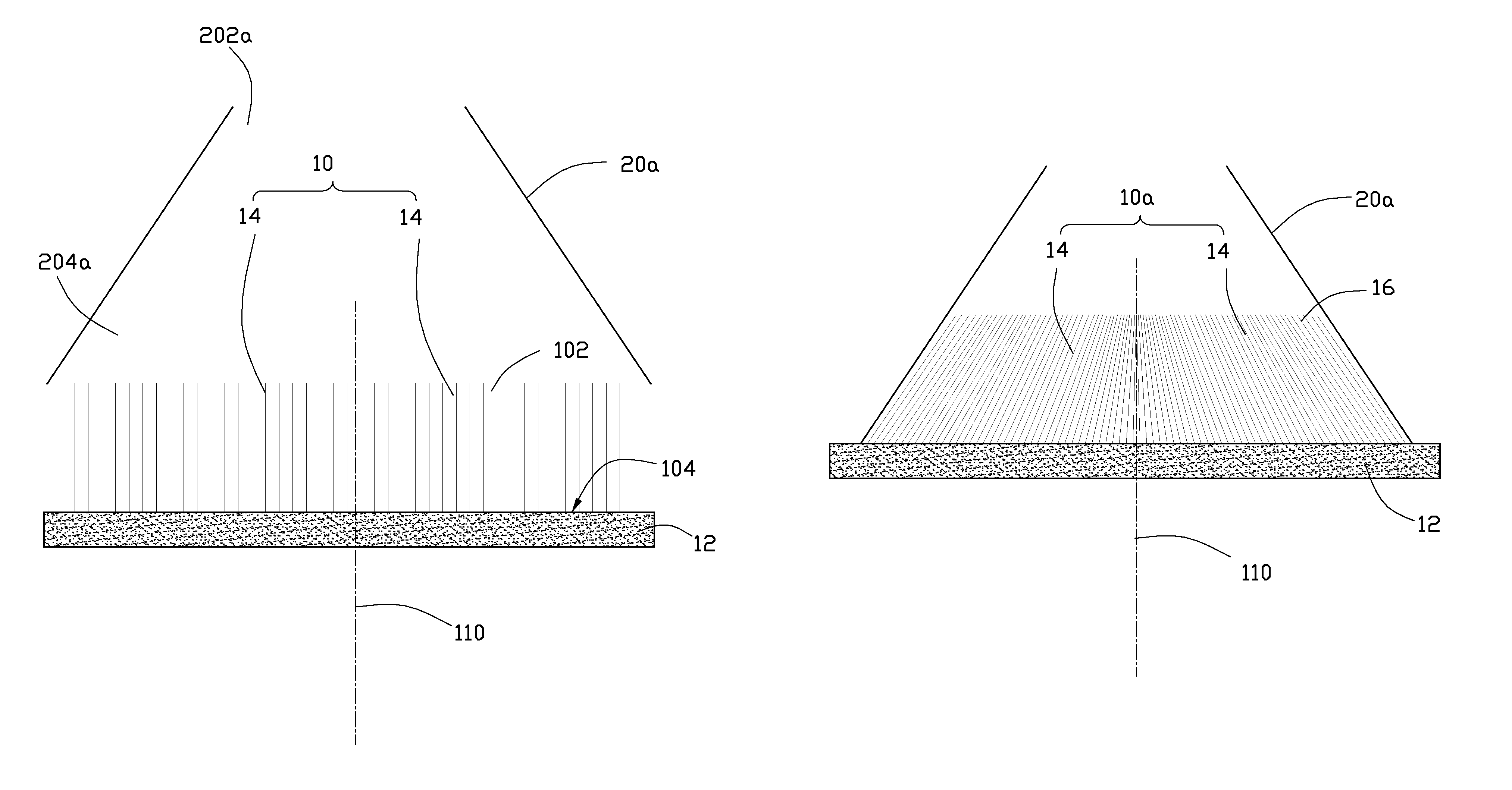
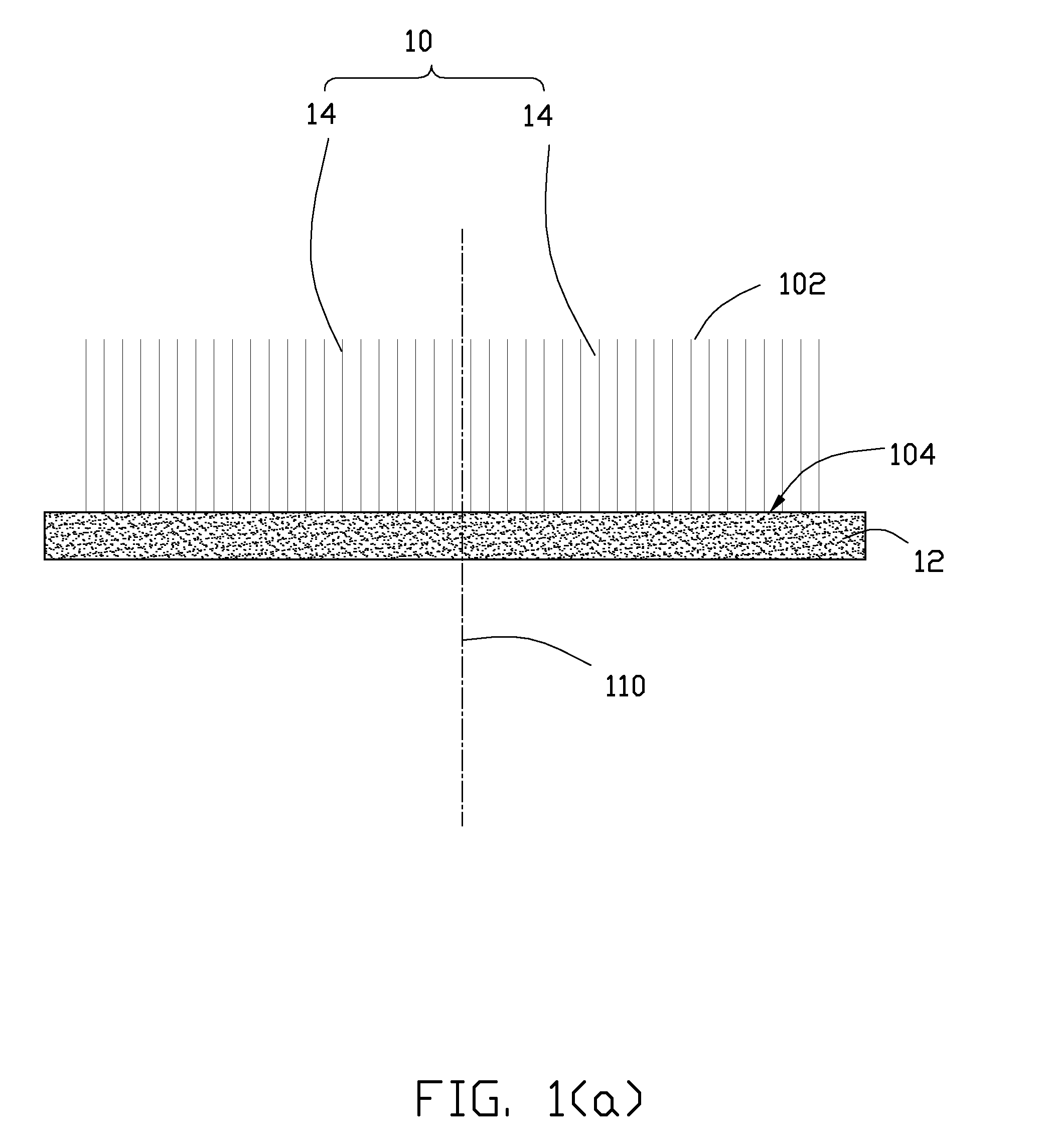
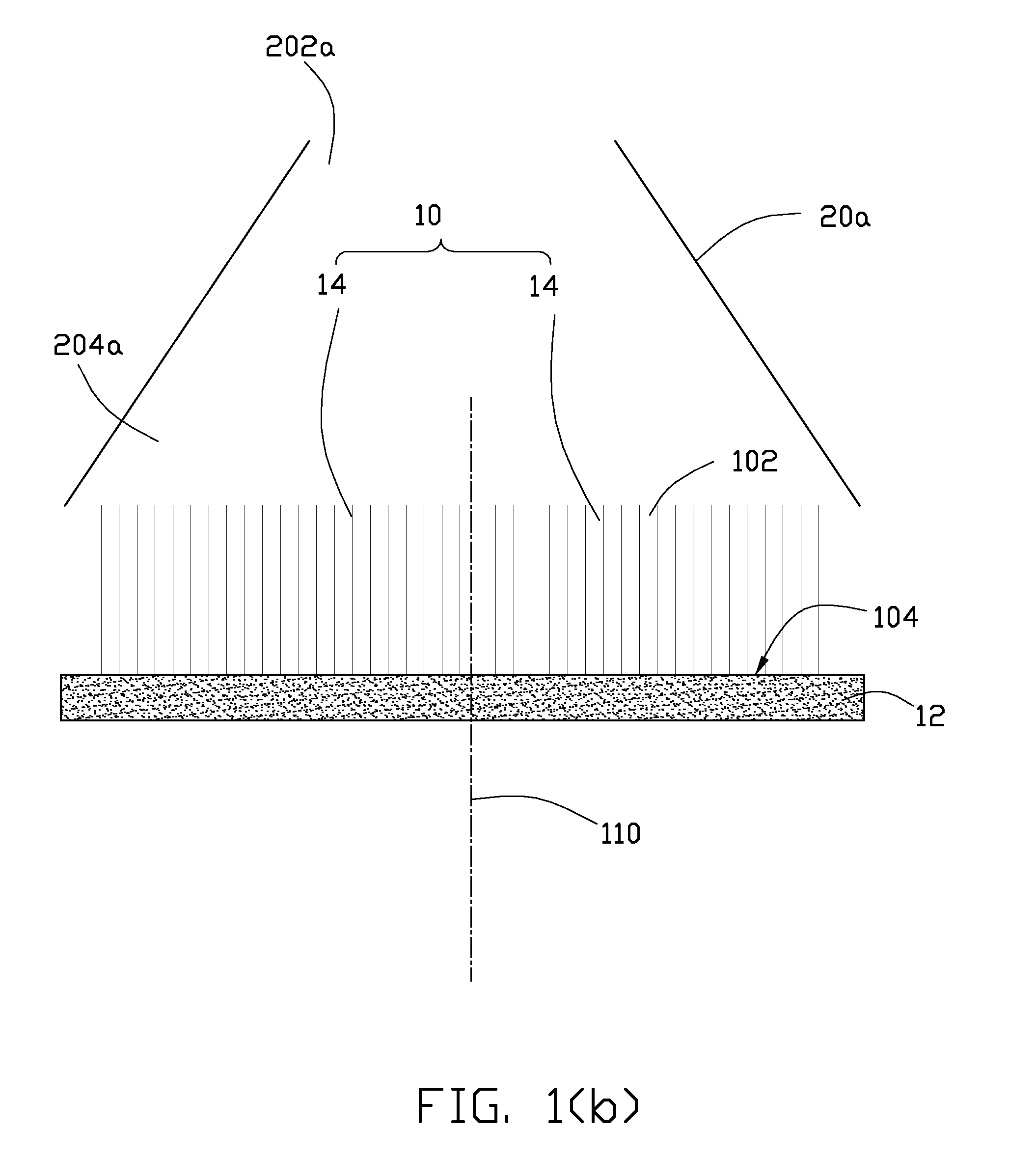
[0015]Referring to FIGS. 1(a) to 1(e), a method for making a thermal interface material 30 according to one embodiment includes:

[0016](a) providing a carbon nanotube array 10 on a substrate 12, the carbon nanotube array 10 including a plurality of carbon nanotubes 14 substantially parallel to each other and substantially perpendicular to the substrate 12;

[0017](b) slanting the carbon nanotubes 14 of the carbon nanotube array 10 toward a central axis 110 of the carbon nanotube array 10;

[0018](c) providing a liquid matrix material 16 and compounding the liquid matrix material 16 with the carbon nanotube array 10; and

[0019](d) solidifying the liquid...


PUM

PropertyMeasurementUnit
temperatureaaaaaaaaaa
melting pointaaaaaaaaaa
thicknessaaaaaaaaaa

Abstract

The present disclosure relates to a method for making a thermal interface material. A carbon nanotube array on a substrate is provided. The carbon nanotube array includes a plurality of carbon nanotubes substantially parallel to each other and substantially perpendicular to the substrate. The carbon nanotubes of the carbon nanotube array are slanted toward a central axis of the carbon nanotube array. A liquid matrix material is compounded with the carbon nanotube array. Additionally, the liquid matrix material is solidified.

Description

CROSS-REFERENCE TO RELATED APPLICATIONS[0001]This application claims all benefits accruing under 35 U.S.C. §119 from China Patent Application No. 200910105874.2, filed on Mar. 2, 2009 in the China Intellectual Property Office, the disclosure of which is incorporated herein by reference.BACKGROUND[0002]1. Technical Field[0003]The present disclosure relates to a method for making a thermal interface material.[0004]2. Description of Related Art[0005]Electronic components such as semiconductor chips are becoming progressively smaller, while at the same time heat dissipation requirements thereof are increasing. Commonly, a thermal interface material is utilized between the electronic component and an integrated heat spreader to dissipate heat generated by the electronic component. However, the performance of the thermal interface material is restricted by a heat conduction coefficient thereof. Heat conduction coefficients of thermal interface materials are now considered to be too low fo...

Claims


Application Information

Patent Timeline
Patent Type & Authority Patents(United States)
IPC IPC(8): B29C39/10B29C45/14
CPCH01L23/373H01L23/433H01L2924/0002H01L2924/00
Inventor YAO, YUANDAI, FENG-WEIWANG, JI-CUNZHANG, HUI-LINGWANG, YOU-SENLIU, CHANG-HONG
Owner TSINGHUA UNIV
Why Eureka
Try Eureka