3 transistors 4 shared step and repeat unit cell and 3 transistors 4 shared image sensor including the unit cells

a technology of image sensor and unit cell, which is applied in the field of image sensor, can solve the problems of four image sensor circuits combined in a single unit cell, and have not been particularly published

Active Publication Date: 2012-07-17
SK HYNIX INC
View PDF9 Cites 32 Cited by
  • Summary
  • Abstract
  • Description
  • Claims
  • Application Information

AI Technical Summary

Problems solved by technology

However, a case where four image sensor circuits combined in a single unit cell has not been particularly published.

Method used


Image

  • 3 transistors 4 shared step and repeat unit cell and 3 transistors 4 shared image sensor including the unit cells
  • 3 transistors 4 shared step and repeat unit cell and 3 transistors 4 shared image sensor including the unit cells
  • 3 transistors 4 shared step and repeat unit cell and 3 transistors 4 shared image sensor including the unit cells

Examples


first embodiment

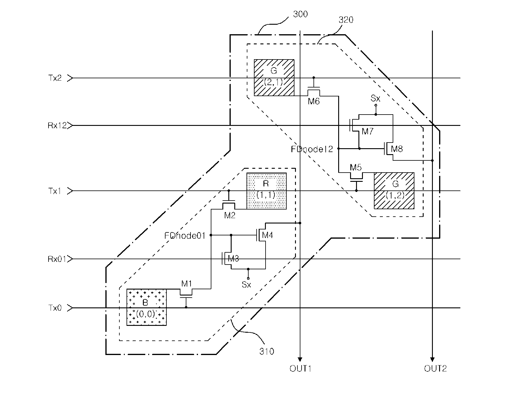
[0034]FIG. 3 illustrates a 3T-4S step & repeat unit cell according to the present invention.

[0035]Referring to FIG. 3, a 3T-4S step & repeat unit cell 300 includes first and second shared image sensor unit cells 310 and 320.

[0036]The 3T-4S step & repeat unit cell 300 includes a first photodiode (0, 0), a second photodiode (1, 1) disposed in a diagonal direction of the first photodiode (0, 0), a third photodiode (1, 2) disposed in the right side of the second photodiode (1, 1), and a fourth photodiode (2, 1) disposed over the second photodiode (1, 1). Although not shown, a terminal of each of the four photodiodes (0, 0) to (2, 1) is connected to a ground voltage (GND).

[0037]The first shared image sensor unit cell 310 includes two photodiodes (0, 0) and (1, 1) and four MOS transistors M1 to M4.

[0038]A first transmission transistor M1 has a terminal connected to the other terminal of the first photodiode (0, 0) and a gate applied with a first transmission signal Tx0. A second transmiss...

second embodiment

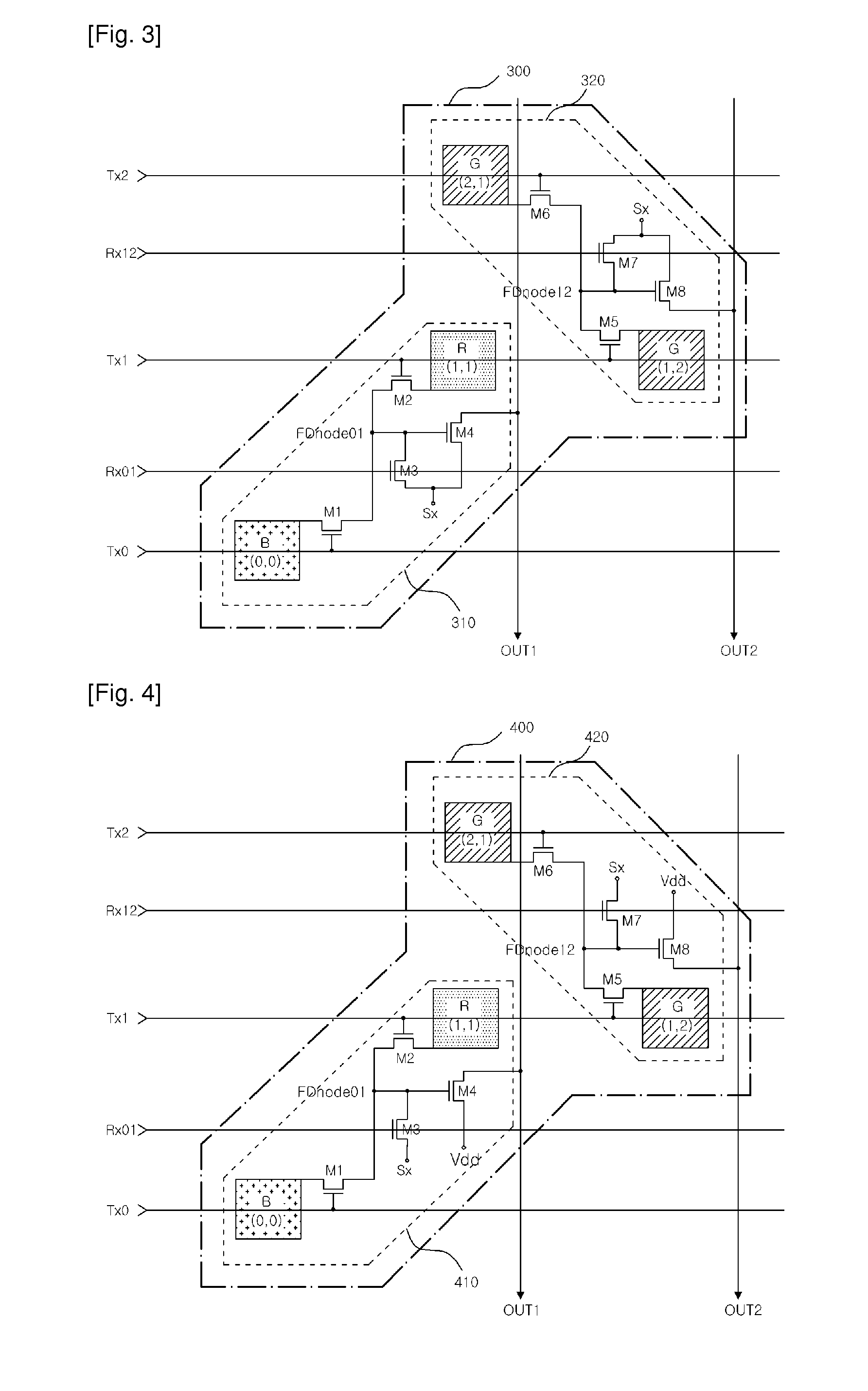
[0041]FIG. 4 illustrates a 3T-4S step & repeat unit cell according to the present invention.

[0042]Referring to FIG. 4, a 3T-4S step & repeat unit cell 400 is the same as the 3T-4S step & repeat unit cell 300 shown in FIG. 3 except connection of a terminal of each of the conversion transistors M4 and M8. The first and second shared image sensor unit cells 310 and 320 correspond to first and second shared image sensor unit cells 410 and 420.

[0043]In FIG. 3, a terminal of each of the two conversion transistors M4 and M8 constituting the unit cell 300 is connected to the selection signal Sx. In FIG. 4, a terminal of each of the two conversion transistors M4 and M8 constituting the unit cell 400 is connected to a voltage source Vdd. Here, the voltage source Vdd is a voltage source having a high voltage level among voltage sources used to operate a system on which the unit cell 400 is mounted. In this case, a voltage level obtained when the selection signal Sx is enabled may have the same...

third embodiment

[0044]FIG. 5 illustrates a 3T-4S step & repeat unit cell according to the present invention.

[0045]Referring to FIG. 5, a 3T-4S step & repeat unit cell 500 includes first and second shared image sensor unit cells 510 and 520.

[0046]The 3T-4S step & repeat unit cell 500 includes a first photodiode (0, 0), a second photodiode (1, 0) disposed over the first photodiode (0, 0), a third photodiode (1, 1) disposed in the right side of the second photodiode (1, 0), and a fourth photodiode (2, 1) disposed over the third photodiode (1, 1). Although not shown, a terminal of each of the four photodiodes (0, 0) to (2, 1) is connected to a ground voltage (GND).

[0047]The first shared image sensor unit cell 510 includes two photodiodes (0, 0) and (1, 1) and four MOS transistors M1 to M4.

[0048]A first transmission transistor M1 has a terminal connected to the other terminal of the photodiode (0, 0) and a gate applied with a first transmission signal Tx0. A second transmission transistor M2 has a termi...


PUM


Abstract

A 3T-4S step & repeat unit cell obtained by combining four image sensor unit cells each including three transistors and a 3T-4S image sensor including the 3T-4S step & repeat unit cell are provided. The 3T-4S step & repeat unit cell includes first to fourth photodiodes. A first shared image sensor unit cell is obtained by combining the first and second photodiodes with four transistors. A second shared image sensor unit cell is obtained by combining the third and fourth photodiodes with four transistors. Signals corresponding to images incident onto the first and second photodiodes are output through a first common detection line. Signals corresponding to images incident onto the third and fourth photodiodes are output through a second common detection line. A terminal of each of the four photodiodes is connected to a first voltage source. Conversion voltages corresponding to image signals incident onto two photodiodes via green filters are output through a common detection line. Conversion voltages corresponding to image signals incident onto the other two photodiodes via red and blue filters are output through another common detection line.

Description

TECHNICAL FIELD[0001]The present invention relates to an image sensor, and more particularly, to a 3T-4S step & repeat unit cell obtained by combining four image sensor unit cells each including three transistors.BACKGROUND ART[0002]FIG. 1 illustrates a 3T-2S image sensor circuit obtained by combining two first-type image sensor circuits each including three transistors.[0003]Referring to FIG. 1, a 3T-2S image sensor circuit 100 is obtained by combining two image sensor unit cells 110 and 120 each including three transistors. The 3T-2S image sensor includes two photodiodes PD0 and PD1 and four transistors M101 to M104. In the 3T-2S image sensor circuit 100, reset transistors M2 and M5 and conversion transistors M3 and M6 are shared by the two image sensor circuits 110 and 120 each including three transistors. The 3T-2S image sensor circuit 100 uses two transistors M103 and M104 commonly used for reset and conversion operations and two transmission transistors M101 and M102 respectiv...

Claims


Application Information

Patent Timeline
Patent Type & Authority Patents(United States)
IPC IPC(8): H04N3/14H04N5/335H04N5/3745
CPCH01L27/14641H04N25/778H04N25/77
Inventor LEE, DO-YOUNG
Owner SK HYNIX INC
Why Eureka
Try Eureka