Device for non-dissipative measurement of the current in an inductor

a current measurement and inductor technology, applied in the direction of electric variable regulation, process and machine control, instruments, etc., can solve the problems of affecting the overall efficiency of the converter, affecting the accuracy of the measurement, and the current measurement which is obtained exhibiting an error related to the temperature, so as to improve the operation of the device and increase the precision

Active Publication Date: 2007-04-05
THALES SA
View PDF9 Cites 171 Cited by
  • Summary
  • Abstract
  • Description
  • Claims
  • Application Information

AI Technical Summary

Benefits of technology

[0042] A capacitor C1′ may be added in parallel with R3 and R4 so a

Problems solved by technology

This solution has the advantage of being simple to implement, on the other hand it has a major drawback.
Specifically, the power dissipated in the shunt contributes to a degradation in the overall efficiency of the converter, which is not always acceptable, this being all the more true when the output voltage of the energy conversion device is low.
However the device of the prior art represented in FIG. 2, has a major drawback since the value of the resistance RL of the inductor depends on the temperature to which it is subjected, the cur

Method used


Image

  • Device for non-dissipative measurement of the current in an inductor
  • Device for non-dissipative measurement of the current in an inductor
  • Device for non-dissipative measurement of the current in an inductor

Examples


Embodiment Construction

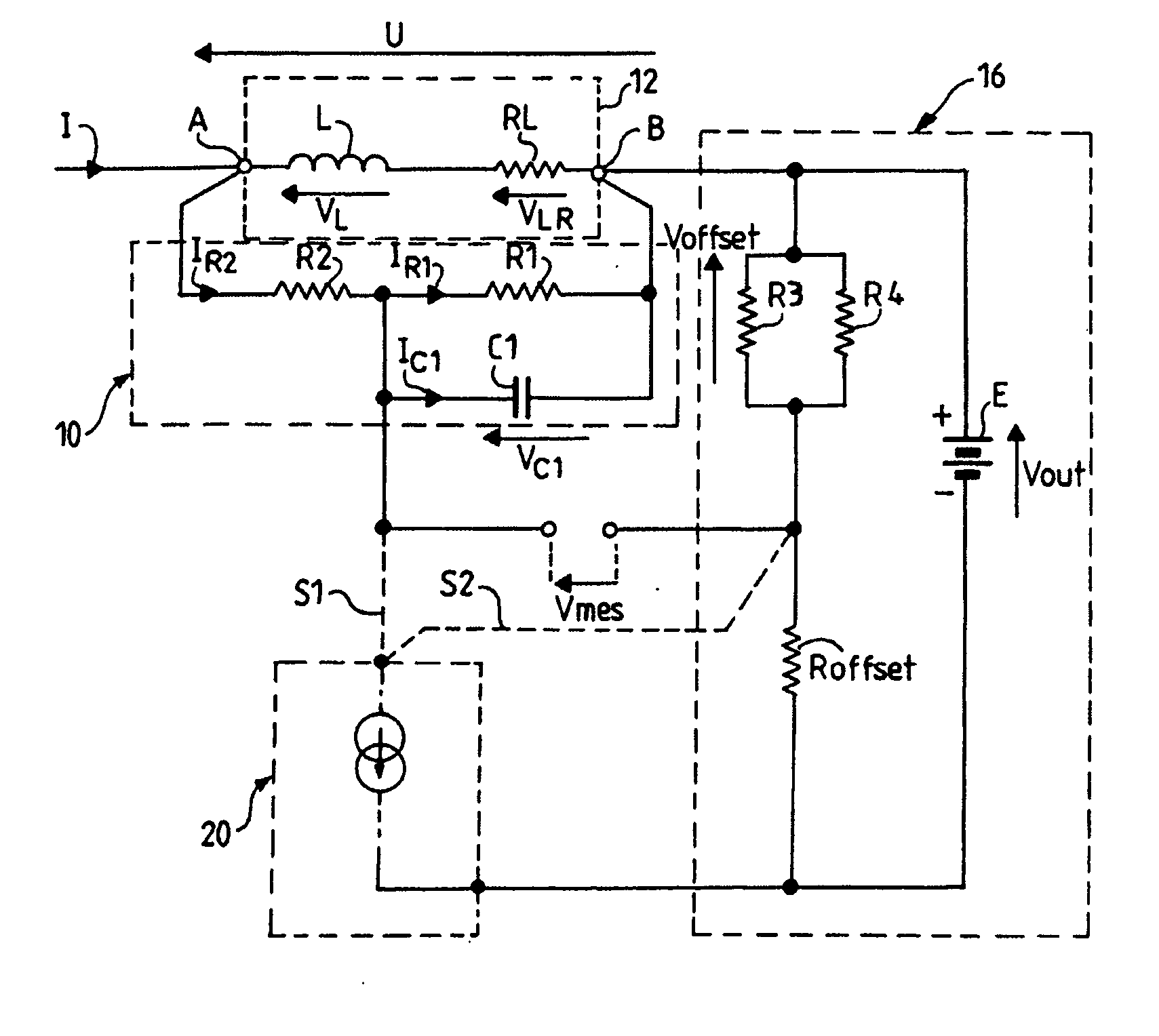
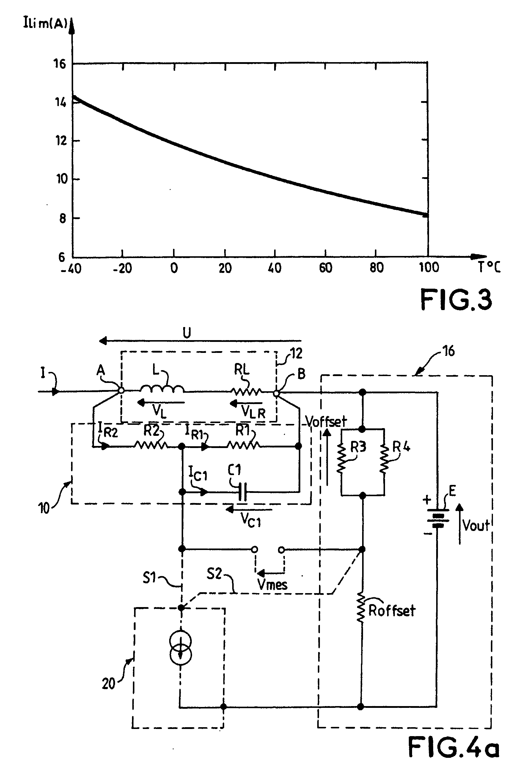
[0051] The diagram of FIG. 4a shows a device for measuring current in an inductor in a general case of the invention with a voltage offset.

[0052]FIG. 4a shows: [0053] the inductor 12 represented by its equivalent diagram comprising a pure reactive part L, in series with a resistor RL; [0054] a device for measuring current in the inductor 12, according to the invention, connected in parallel with the inductor comprising the two terminals A and B.

[0055] The device of FIG. 4a comprises: [0056] the network 10 as represented in FIG. 2 (or the measurement device of the state of the art of FIG. 1) in parallel with the inductor 12 and connected to the terminals A and B having the resistor R2 in series with the resistor R1 in parallel with the capacitor C1; [0057] a voltage offset circuit 16 having the generator E of DC voltage Vout connected in parallel with the offset resistor Roffset in series with the two resistors in parallel R3 and R4 and to the common point of the resistor R1 and th...


PUM


Abstract

The invention relates to a device for measuring current in an inductor, which device is intended to be connected in parallel with said inductor, comprising two terminals A and B. The device comprises: a network in parallel with the inductor and connected to the terminals A and B having a resistor R2 in series with a resistor R1 in parallel with a capacitor C1; a voltage offset circuit having a DC voltage generator E connected in parallel with an offset resistor (Roffset) in series with two resistors in parallel R3 and R4, the positive pole of this voltage source being connected to terminal B of the inductor; a temperature compensation circuit comprising a current source controlled as a function of the temperature, one of the two terminals of the current source being connected to the negative pole of the generator E, the other terminal of the current source being connected to different points of the measurement device according to the direction of variation of the current of the source as a function of the temperature. The measurement of voltage Vmes, the image of the current I in the inductor 12, is performed between the common point between the resistors R1, R2 of the network and the common point between the offset resistor and the two resistors R3 and R4.

Description

FIELD OF THE INVENTION [0001] The invention relates to an inexpensive and compact non-dissipative measurement device for the current flowing through an inductor inserted into an electrical or electronic device. BACKGROUND OF THE INVENTION [0002] In certain electronic applications it is necessary to measure the value of the current in the inductors with good accuracy and while disturbing as little as possible the device in which the inductor is inserted. We may cite for example the measurement of the current in the inductors of switched mode power supplies, among other things, voltage step-down or step-up switched mode serial choppers (respectively known as “buck converters” and “boost converters”). [0003] The conventional method which is most used consists in placing a measurement shunt in series with the inductor, thereby making it possible to obtain the image of the current in the inductor by measuring the voltage across the terminals of the shunt. This solution has the advantage ...

Claims


Application Information

Patent Timeline
IPC IPC(8): G01R27/08G01R19/00G01R19/32
CPCG01R19/0092G01R19/32G01R1/203
Inventor BLANC, FLAVIENTAURAND, CHRISTOPHE
Owner THALES SA
Why Eureka
Try Eureka