Airborne reconnaissance system

a reconnaissance system and airborne technology, applied in the field of airborne reconnaissance systems, can solve the problems of significantly increasing flying costs and risks, delay dominated by aircraft progression, and length of time required for film developmen

Active Publication Date: 2012-07-17
STATE OF ISRAEL MINIST OF AGRI & RURAL DEV AGRI RES ORG (A R O) (VOLCANI CENT)
View PDF10 Cites 2 Cited by
  • Summary
  • Abstract
  • Description
  • Claims
  • Application Information

AI Technical Summary

Benefits of technology

[0028]Preferably, cross-talk between any two of said separate images which are produced on the focal plane array is eliminated by ignoring portions of the focal plane array at locations between the separate images.

Problems solved by technology

The main problem of an airborne, film-camera based reconnaissance system is the length of time required for developing the film, an operation that can be performed only after landing.
The need for securing the reconnaissance aircraft, while flying above or close to hostile areas, has significantly increased flying costs and risks, as sometimes the reconnaissance mission requires escorting of the aircraft by other, fighter aircrafts.
There are several other problems generally involved in carrying out airborne reconnaissance.
In that case, however, the first row of the array captures an area strip, while the subsequent rows are used to capture the same strip, but at a delay dominated by the aircraft progression.
A significant problem which is characteristic to all the above types of prior art reconnaissance systems is their limited field of view.
Any attempt to increase the field of view results in a significant reduction in the resolution of the captured image.
However, such an approach requires a very expensive, heavy, and complicated mechanism.
Moreover, such mechanical scanning could have been performed at a limited rate due to its structure, and in order to fully scan the area as required, the maximal flight velocity of the aircraft was limited.
This limitation of the flight velocity is a very significant drawback, as reconnaissance missions are generally performed over enemy territory.
Still a significant drawback of reconnaissance systems of the prior art, for example, U.S. Pat. No. 5,155,597, U.S. Pat. No. 5,692,062, WO 97 / 42659, U.S. Pat. No. 6,130,705, and U.S. Pat. No. 6,256,057 is their limited ability to capture images in a wide range of a field of regard.
Systems of the prior art sometimes use several dedicated systems for different sight directions (e.g. a separate system for down-looking, and others for side-oblique looking), which significantly increase the cost and weight of the whole reconnaissance system.

Method used


Image

  • Airborne reconnaissance system
  • Airborne reconnaissance system
  • Airborne reconnaissance system

Examples


Embodiment Construction

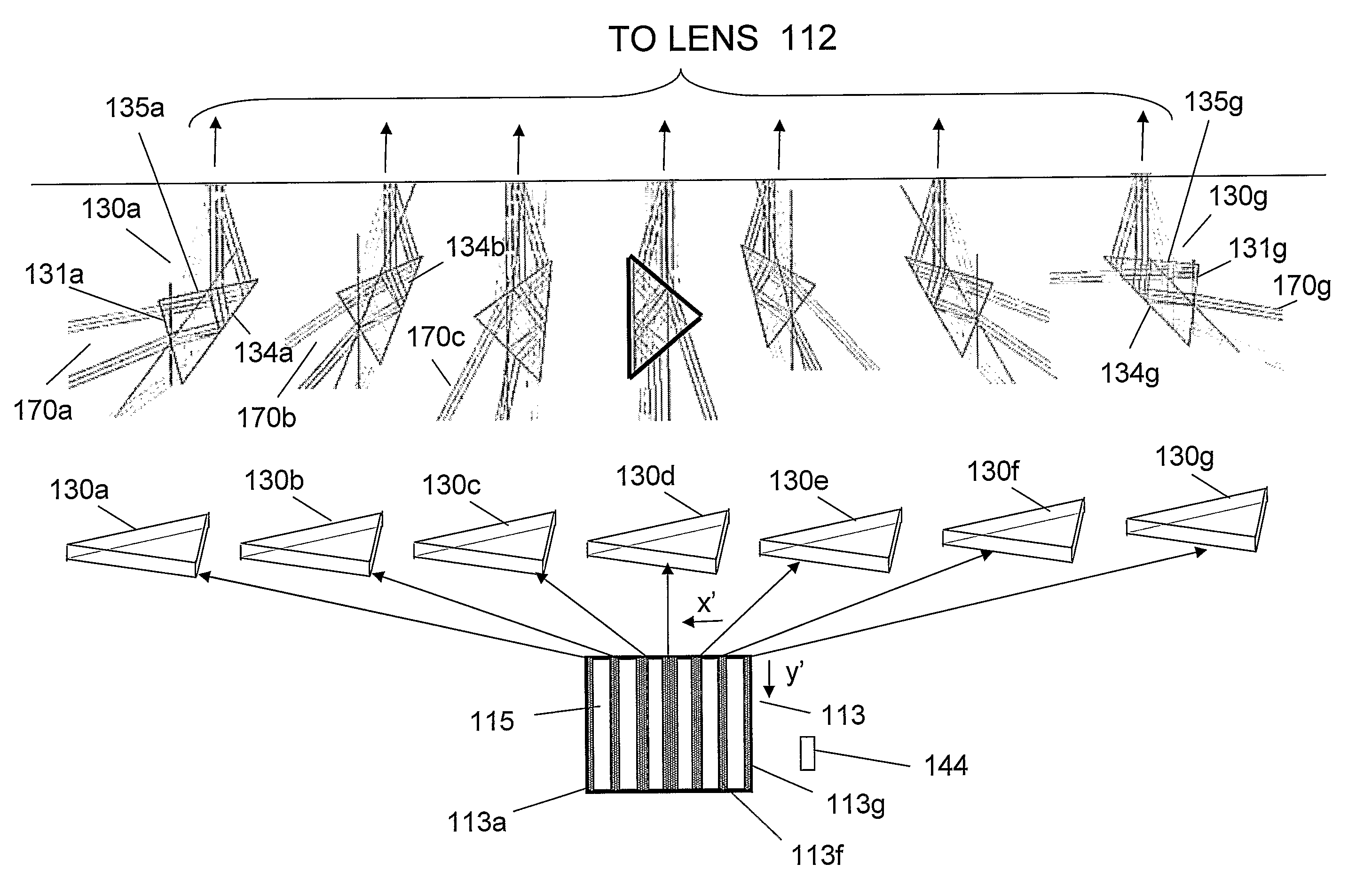
[0047]As said, an object of the airborne reconnaissance system of the present invention is to increase the rate of capturing of terrain images, in a wide field of regard while eliminating the mechanism for changing the view direction of the camera, while still maintaining relatively high image resolution. The invention is particularly useful for carrying out reconnaissance in conditions when the rate V / H is high.

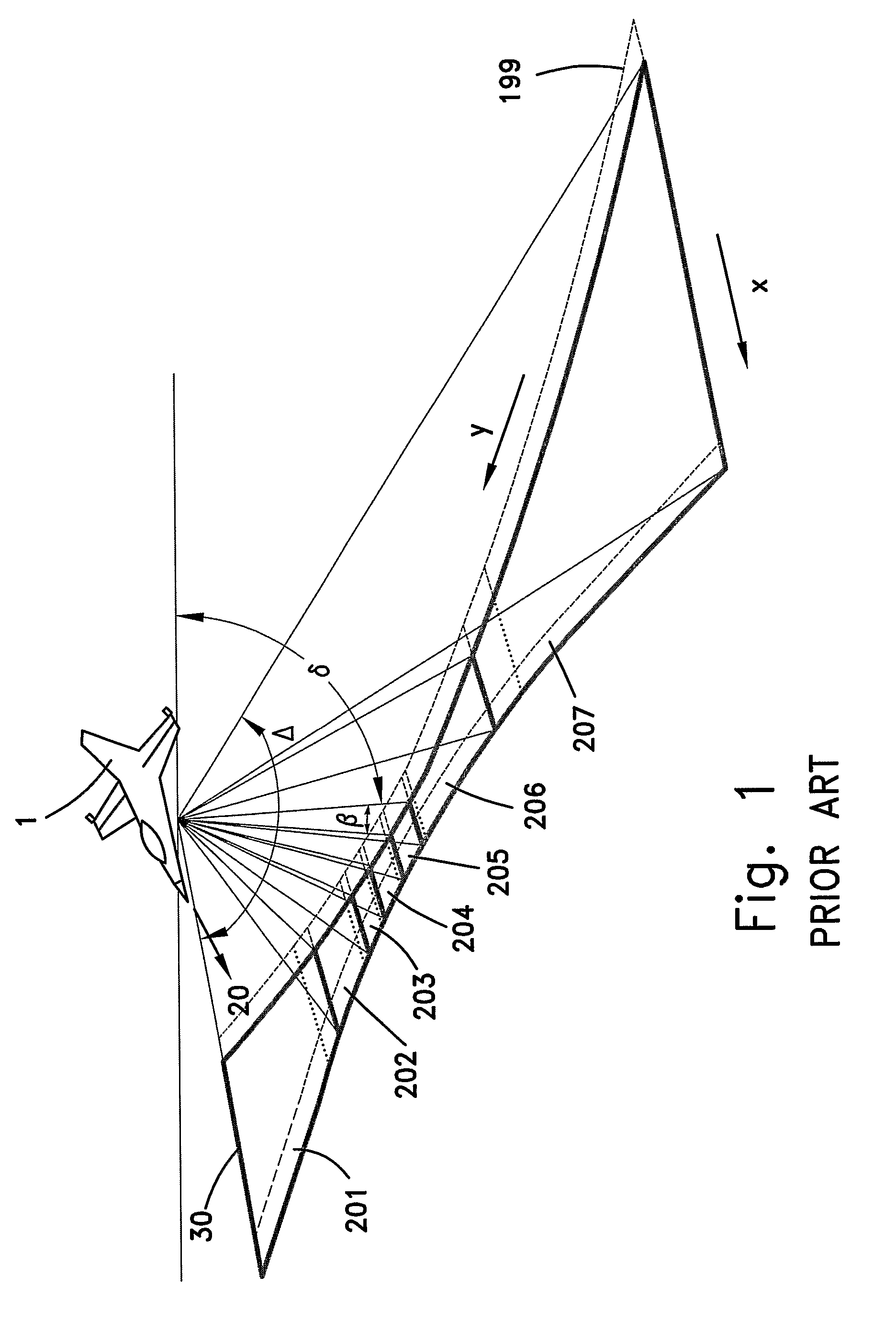
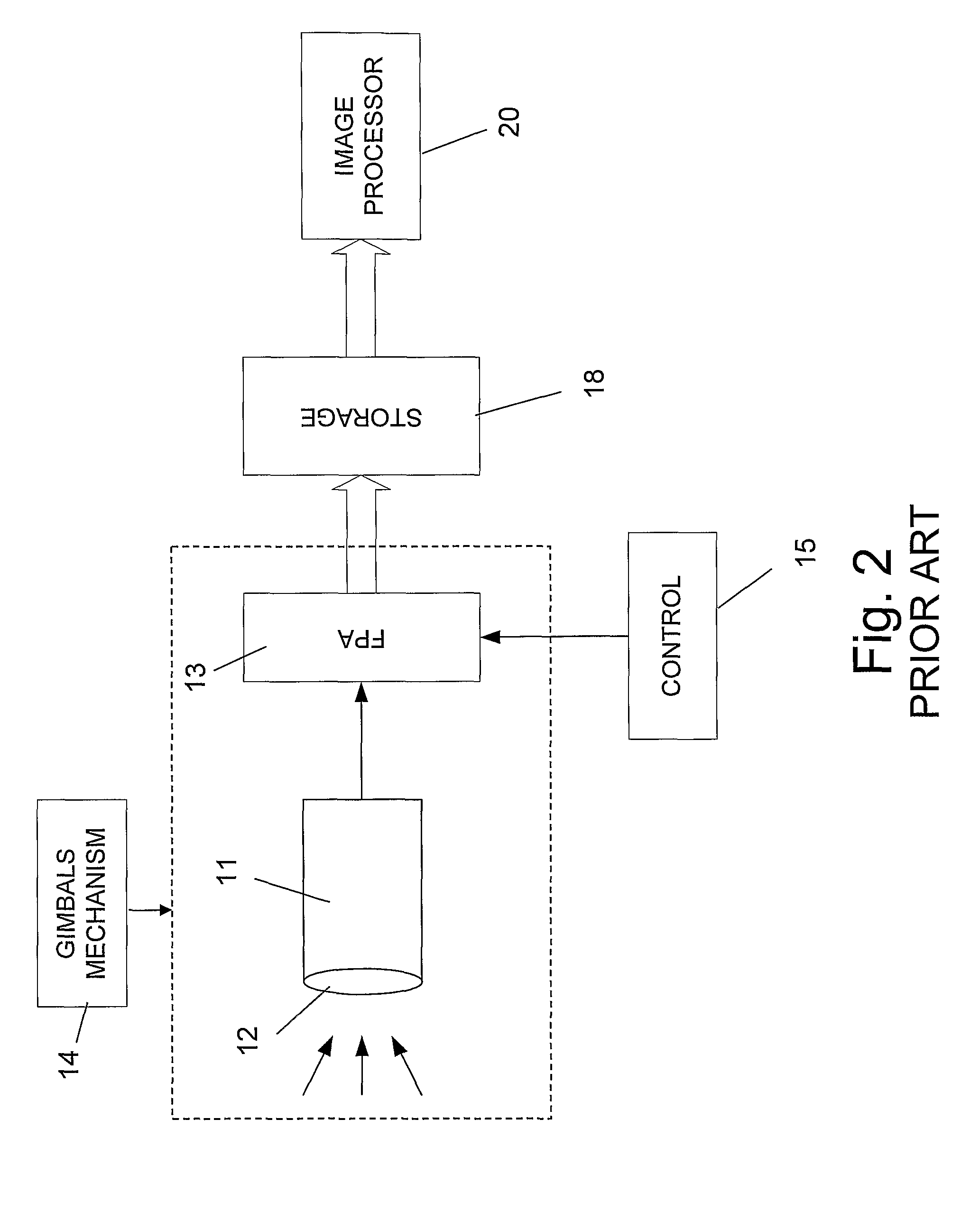
[0048]A typical airborne reconnaissance system of the prior art is shown in FIG. 1. Aircraft 1, provided with an imaging system (not shown) flies in a direction as marked by arrow 20. The imaging system generally comprises a camera for capturing images of terrain 30. Such a camera briefly comprises optics, some type of sensing means such as a focal plane array, and images storage, generally digital storage for storing the captured images. The optics of the system, and the sensing means (generally in a form of a focal plane array) are typically mounted on gimbals mechanism wh...


PUM


Abstract

The present invention relates to an airborne reconnaissance system for capturing images in a wide field of regard which comprises: (a) An array of a plurality of n prisms being one next to the other, each prism having an essentially flat and rectangular front surface, and at least an output surface wherein: (a1) a front surface of each of the plurality of prism is being directed toward a different section of a strip of terrain transversal to the flight direction of the aircraft, thereby collecting light rays coming mostly from that terrain strip section; (a2) each output surface of each of the prisms directs light rays which are received through said front prism surface toward a front lens of an optical unit; (b) A focal plane array; (c) Optical unit comprising a front lens, the front lens receiving light separately but simultaneously through the output surfaces of all the prisms, said optical unit comprises addition optics for directing the light received from said lens thereby to produce separate corresponding prism images on said focal plane array; (d) Control unit for periodically capturing all the images that are produced on the focal plane array at each instant, and transferring them into an electronic storage; and (e) Processing and combining unit for processing and combining all the separate stored prism images into a full image of the terrain relating to said wide field of regard.

Description

FIELD OF THE INVENTION[0001]The field of the present invention relates to a system for carrying out airborne reconnaissance. More particularly, the present invention relates to an airborne reconnaissance system which can obtain images in a wider field of view in comparison with similar prior art systems, without sacrificing the images resolution. Furthermore, the system of the present invention obtains such a wider field of view with no use of gimbals, or any other equivalent dynamic mechanical system for changing the direction of the field of view.BACKGROUND OF THE INVENTION[0002]Airborne reconnaissance systems have been widely used for many years now, particularly for obtaining images from the air of areas of interest.[0003]Originally, a film camera was used on board of the aircraft for capturing images of the terrain. The main problem of an airborne, film-camera based reconnaissance system is the length of time required for developing the film, an operation that can be performed ...

Claims


Application Information

Patent Timeline
Patent Type & Authority Patents(United States)
IPC IPC(8): H04N7/18G01C11/02H04N
CPCG01C11/02G02B13/06
Inventor ROSENBLUM, ELIEZERYAVIN, ZVI
Owner STATE OF ISRAEL MINIST OF AGRI & RURAL DEV AGRI RES ORG (A R O) (VOLCANI CENT)
Why Eureka
Try Eureka