Arc flash detection

a technology of arc flash and detection device, applied in the field of detection device, can solve the problems of delay or no tripping of circuit breakers, device established by regulation to eliminate arc flash, standard fuses and circuit breakers typically do not react quickly enough, etc., and achieve the effect of reducing the intensity of light received

Active Publication Date: 2012-07-17
ABB SPA
View PDF15 Cites 28 Cited by
  • Summary
  • Abstract
  • Description
  • Claims
  • Application Information

AI Technical Summary

Problems solved by technology

However, the arc fault current is usually much less than a short circuit current, and hence delayed or no tripping of circuit breakers is expected unless the breakers are selected to handle an arc fault condition.
Agencies and standards such as the National Environmental Policy Act (NEPA), Occupational Safety and Health Administration (OSHA), and Institute of Electrical and Electronics Engineers (IEEE) regulate arc flash issues through personal protective clothing and equipment, but there is no device established by regulation to eliminate arc flash.
Standard fuses and circuit breakers typically do not react quickly enough to an arc flash.
However, such intentional short circuits may allow significant levels of current resulting from the intentional short-circuit.
Atmospheric and obstacles could change that estimation.
In addition, most sensors become saturated well below the level at which an arc flash event would be emitting.

Method used


Image

  • Arc flash detection
  • Arc flash detection
  • Arc flash detection

Examples


Embodiment Construction

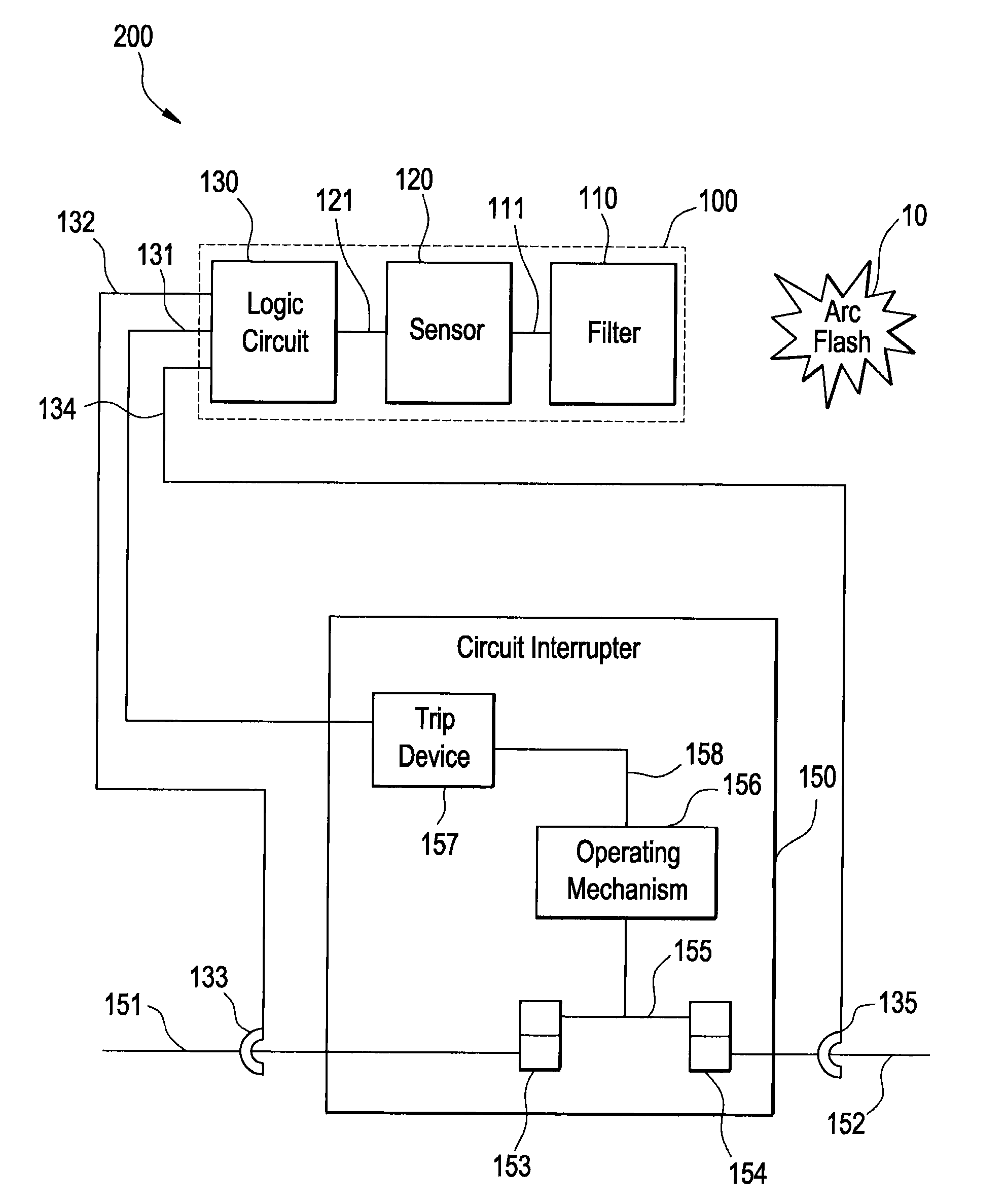
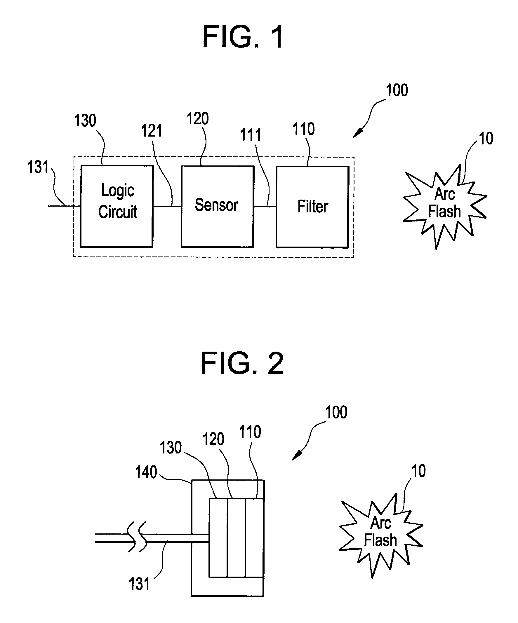
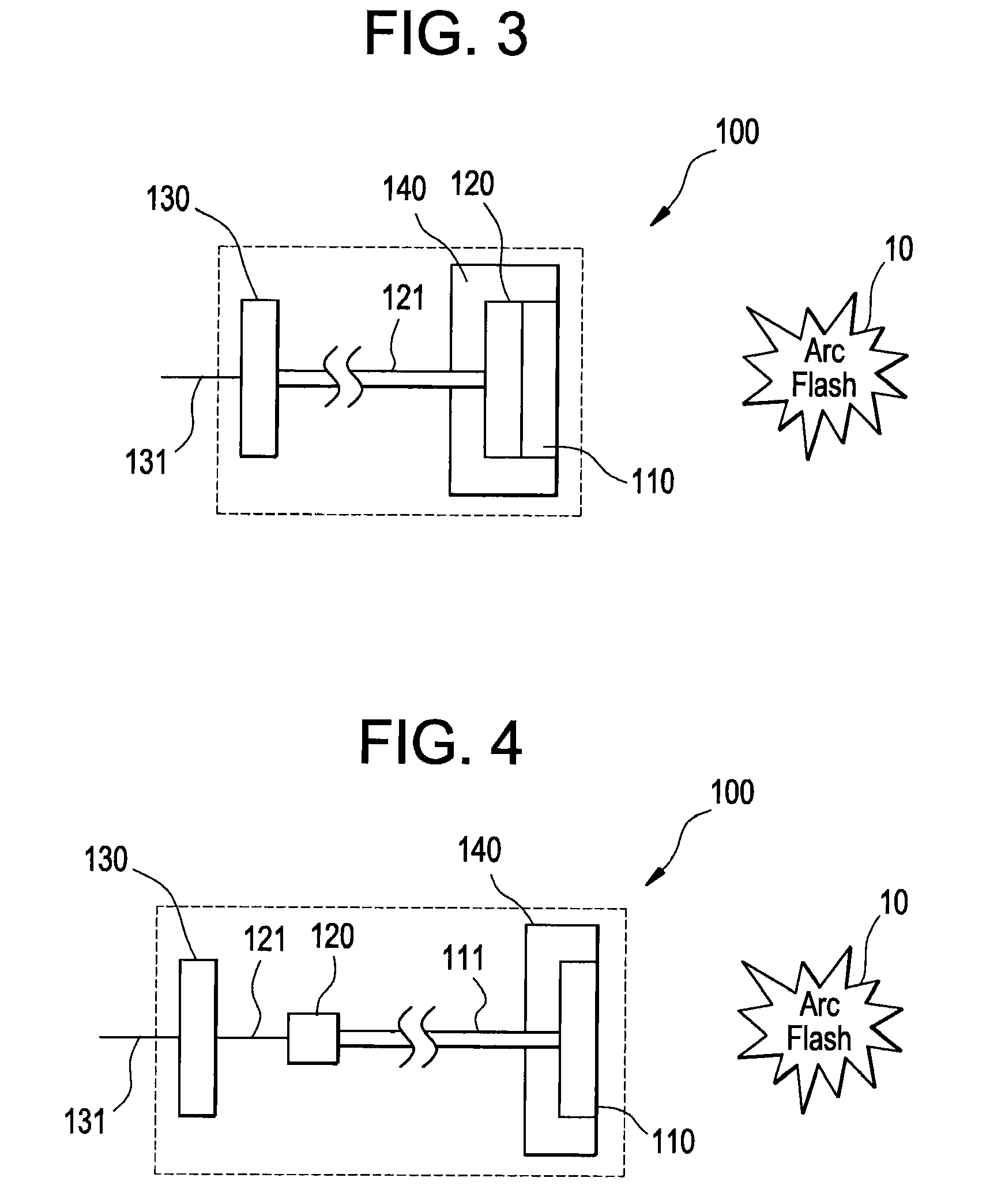
[0024]As schematically illustrated in FIG. 1, an arc flash detector 100 according to an embodiment disclosed herein includes a light attenuating filter 110, a light sensor 120, and a logic circuit 130. Ambient light enters the light attenuating filter 110, which attenuates the ambient light by a predetermined percentage. The attenuated ambient light travels from the light attenuating filter 110 to the light sensor 120. If the attenuated ambient light is of sufficient intensity to saturate the light sensor 120, the light sensor 120 sends an output signal to the logic circuit 130. The logic circuit 130 evaluates the output signal of the light sensor 120 and produces an output signal of its own if it determines that an arc flash event has occurred. The output signal of the logic circuit 130 is then used by another device to stop the arc flash, to alert an operator, and / or take other action. For example, the light sensor may be powered through a power supply connected thereto. Further, ...


PUM


Abstract

An arc flash detector includes a light sensor, a light attenuating filter in communication with the light sensor, a housing disposed to support the light attenuating filter and the light sensor, and a logic circuit in communication with the light sensor. The logic circuit is disposed to receive an output of the light sensor and disposed to produce an output signal responsive to a predetermined intensity of light received by the light sensor. The light attenuating filter is disposed to reduce the intensity of light received by the light sensor. The housing is also disposed to retain the light sensor and the light attenuating filter at a fixed orientation.

Description

BACKGROUND OF THE INVENTION[0001]The subject matter disclosed herein relates to arc flash detection and mitigation technologies, and particularly relates to detection devices for this purpose.[0002]Electric power circuits and switchgear have conductors separated by insulation. Air space often serves as part or all of this insulation in some areas. If the conductors are too close to each other or voltage exceeds the insulation properties, an arc can occur between conductors. Air or any insulation (gas or solid dielectrics) between conductors can become ionized, making it conductive, which enables arcing. Arc temperature can reach as high as 20,000° C., vaporizing conductors and adjacent materials, and releasing significant energy.[0003]Arc flash is the result of a rapid energy release due to an arcing fault between phase-phase, phase-neutral, or phase-ground. An arc flash can produce high heat, intense light, pressure waves, and sound / shock waves. However, the arc fault current is us...

Claims


Application Information

Patent Timeline
Patent Type & Authority Patents(United States)
IPC IPC(8): H02H3/00
CPCH02H1/0023G01J1/22G01J1/44
Inventor ROSCOE, GEORGE WILLIAM
Owner ABB SPA
Why Eureka
Try Eureka