Joint for use in back reaming

a back reaming and joint technology, applied in the direction of hose connection, shaft equipment, borehole/well accessories, etc., can solve the problems of increasing the abrasion of the joint coupling between the drill string and the tool, increasing the abrasion of the joint, and exposing the tooling to additional wear and tear

Active Publication Date: 2012-07-24
CHARLES MACHINE WORKS
View PDF8 Cites 10 Cited by
  • Summary
  • Abstract
  • Description
  • Claims
  • Application Information

AI Technical Summary

Problems solved by technology

Even during these conditions, joint couplings between a drill string and tool are subjected to severe torque loadings and longitudinal stresses in these operations.
Back reaming exposes the tooling to additional wear, especially the joint coupling.
Additionally, the cuttings or local soils often collapse on the first drill rod and the joint coupling, increasing the abrasion they sustain during the ream and shortening their useful life overall.
This makes the reaming and cutting process easier, but does not provide the joint couplings or drill string with any protective drilling fluid.
Additionally, during the course of any drilling operation, be it forward drilling or back reaming, significant and unavoidable wear occurs on the threading between the male and female ends of the joint coupling, drill string and tooling.
This is a serious problem, because when the threads no longer hold the couplings securely, the worn parts must be replaced.
An existing design, U.S. Pat. No. 6,860,514 addresses this issue by providing re usable threading, but does not address the fundamental vulnerability of the sleeve encasing the joint threadings to abrasion and damage.
Failure of a joint in a horizontal drilling or back reaming operation can result in not only a tool stuck in a borehole or pipe, necessitating costly and time consuming excavation to recover the tool, or form a bore around the location at which the tool was lost, but can prevent separation of the reamer from the drill string in extreme cases of abrasion where the starter rod is worn through to the point of fracture by the abrasive conditions.
This necessitates costly in ground repairs and part replacements.

Method used


Image

  • Joint for use in back reaming
  • Joint for use in back reaming
  • Joint for use in back reaming

Examples


Embodiment Construction

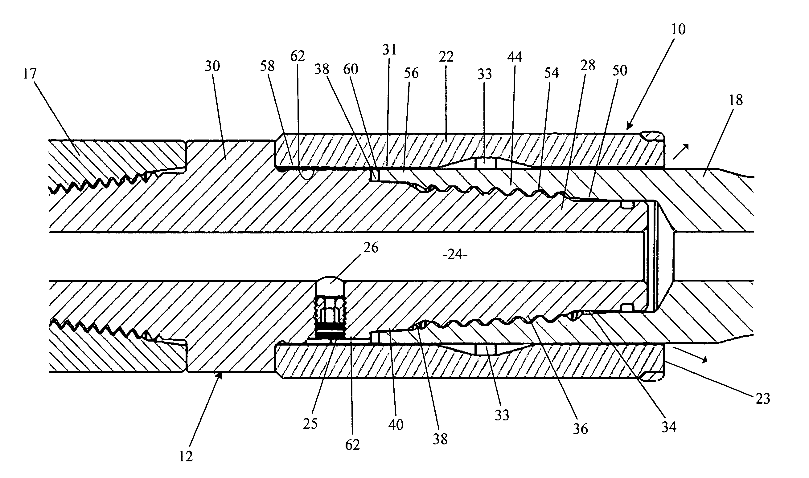
[0018]According to one embodiment of the disclosed invention, drill fluid normally moves down a central path in the drill rod, through the quick connect joint and then finally to the back reamer. In this embodiment of the invention, that central fluid path is tapped with what is effectively a controlled leak that delivers drilling fluid to an annular space within the torque sleeve of the joint preferably through a single metering orifice. The orifice can be sized as needed, or a plug can be used in its place, stopping discharge should conditions not require it. By collecting fluid in the annular space, it allows fluid to be discharged in modest amounts at the leading end or face of the torque sleeve during back reaming operations.

[0019]With a system flow rate during back reaming in the range of 10 to 50 gallons per minute, approximately 1 to 3 gallons per minute (about 5% to 30%) will be sidetracked to for discharge at the torque sleeve. In this manner, only a minor fraction (less t...


PUM


Abstract

A joint according to the invention for connecting a pair of members rotatable about a common axis end to end. A sleeve has a non circular profile on an inner surface thereof whereby the sleeve can be slidably mounted on non circular exterior surfaces of the first and second members when such surfaces are brought into alignment by rotation of one member relative to the other in a manner effective to pass torque from one member to the other by means of the non circular surfaces. A fluid release passage includes a radial port that extends from the first longitudinal fluid supply passage to a clearance between the sleeve and the first member, which clearance communicates with a second clearance between the sleeve and the second member, which second clearance has a discharge opening.

Description

[0001]This application claims priority of U.S. Provisional Application No. 61 / 126,092, filed May 1, 2008.TECHNICAL FIELD[0002]The invention relates to directional boring and, in particular to an improved joint for connecting tools utilized in directional boring to a drill string.BACKGROUND OF THE INVENTION[0003]Directional boring apparatus for making holes through soil are well known. The directional borer generally includes a series of drill rods joined end to end by joint couplings to form a drill string. The drill string is pushed or pulled though the soil by means of a powerful hydraulic device such as a hydraulic cylinder or gear rack mounted on the HDD machine. A drill head for boring in soil, rock or both is attached to the end of the drill string with a joint coupling and may include an ejection nozzle for water or other drilling fluid to assist in boring. In other applications, tools such as reamers, pipe bursters, impact machines, slitters and pullers are attached to the e...

Claims


Application Information

Patent Timeline
Patent Type & Authority Patents(United States)
IPC IPC(8): E21B17/10
CPCE21B10/26E21B17/043E21B21/103
Inventor WENTWORTH, STEVEN W.CRANE, ROBERT F.
Owner CHARLES MACHINE WORKS
Why Eureka
Try Eureka