Check patentability & draft patents in minutes with Patsnap Eureka AI!

Railroad freight car brake beam strut assembly and method of manufacturing same

a technology for brake beams and freight cars, applied in the field of railroad freight cars, can solve the problems of significant disassembly, bushing cracking as they become displaced, and brake levers and related parts of the braking system are subject to vibration and wear,

Active Publication Date: 2012-07-24
MINER ENTERPRISES INC +1
View PDF25 Cites 1 Cited by
  • Summary
  • Abstract
  • Description
  • Claims
  • Application Information

AI Technical Summary

Benefits of technology

The solution effectively inhibits the displacement of brake pin bushings, extending the life of the strut assembly, reducing downtime and maintenance costs by maintaining consistent braking performance and preventing premature condemnation of brake beam assemblies.

Problems solved by technology

During use, a railcar can travel tens of thousands of miles between locations and over railbeds, some of which can be in significant disrepair.
During railcar travel, the brake lever and related parts of the braking system are subject to vibration and wear.
Unless powder sintered metal bushings are properly seated within their respective strut bore, such bushings can crack as they become displaced from their respective strut bore.
Moreover, and even if such brake pin bushings remain partially seated in the strut bore, the powder sintered metal bushing is prone to chipping.
Moreover, and under the rules of the American Association of Railroads (the “AAR”), bushing wear and cracking can result in condemnation of the brake beam assembly.
Only after a suitable repair facility has been identified and becomes available, can replacement of a condemned brake beam assembly be affected.
Replacing a railcar brake beam assembly, for whatever reason, can be a time consuming process.
Moreover, the valuable time lost in separating the railcar with the condemned brake beam from the remaining cars in the train consist, coupled with the time lost in scheduling a repair facility to accomplish replacement of the brake beam assembly, and the valuable time lost in affecting the repair or replacement of the condemned brake beam, along with the time lost in having to move the car with the condemned brake beam to the repair facility for replacement of the brake beam assembly are other considerations and unrealized costs involved with replacing a condemned brake beam.

Method used


Image

  • Railroad freight car brake beam strut assembly and method of manufacturing same
  • Railroad freight car brake beam strut assembly and method of manufacturing same
  • Railroad freight car brake beam strut assembly and method of manufacturing same

Examples


Embodiment Construction

[0052]While the present disclosure is susceptible of embodiment in multiple forms, there is shown in the drawings and will hereinafter be described preferred methods of manufacture, and the present disclosure is to be considered as setting forth exemplifications of various embodiments and methodologies which are not intended to limit the disclosure to the specific embodiments illustrated and methodologies described.

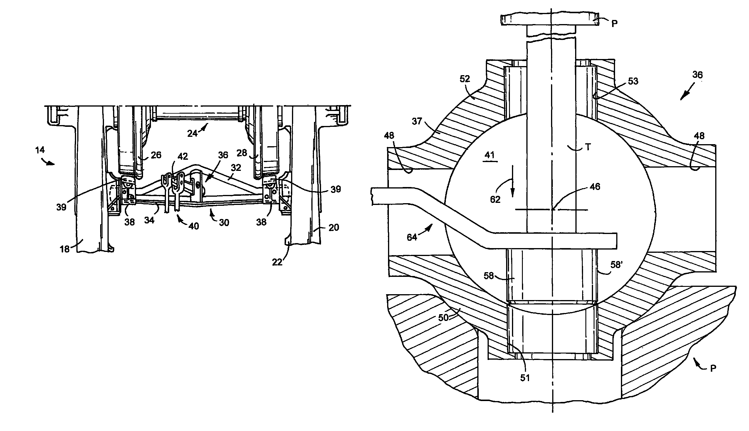
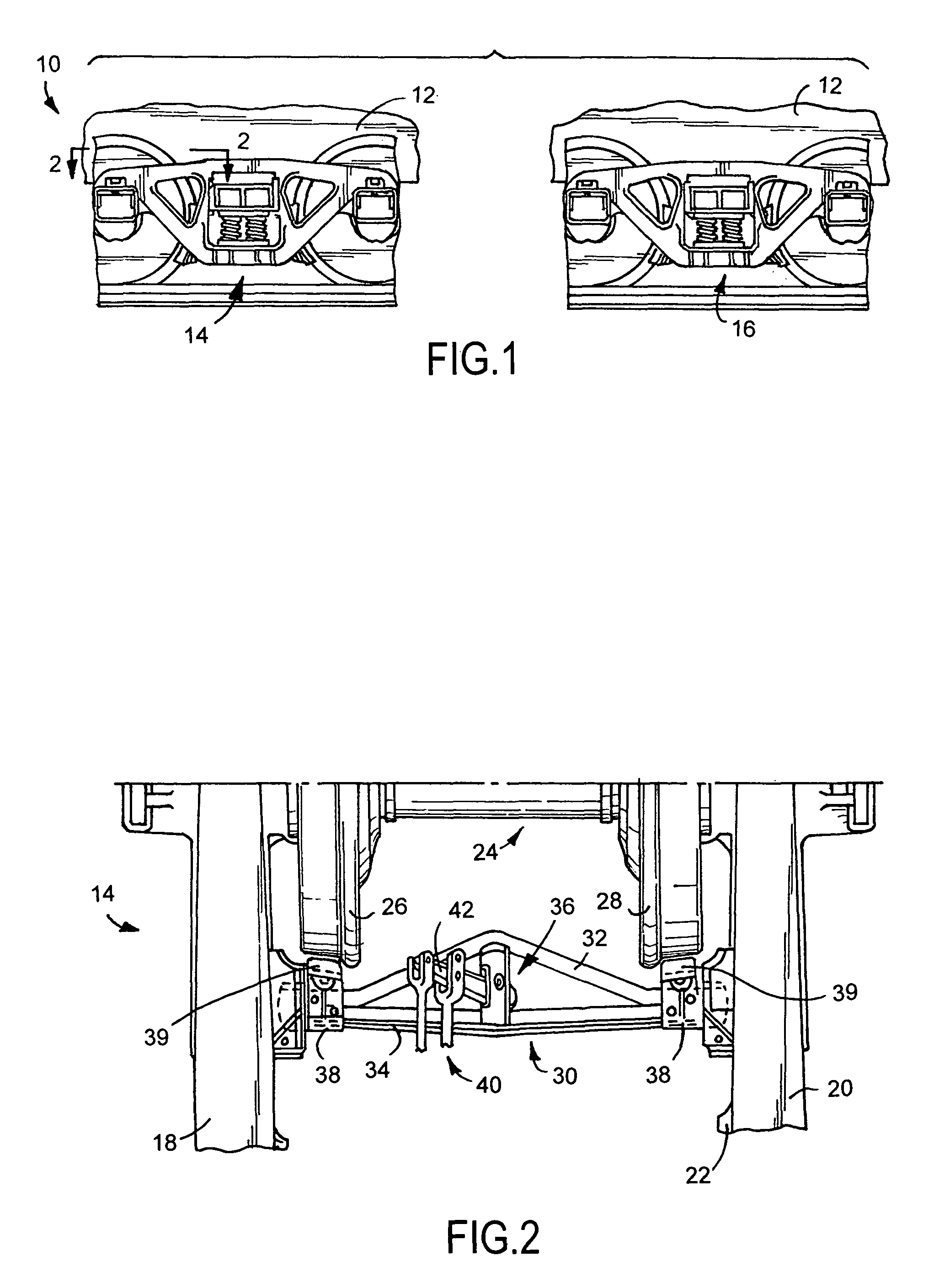
[0053]Referring now to the drawings, wherein like reference numerals indicate like parts throughout the several views, FIG. 1 shows a railroad freight car 10 including a car body 12. Typically, the car body 12 is supported, toward opposite ends and in operable combination with a pair of wheeled trucks 14 and 16 for movement over tracks T. The wheeled trucks 14 and 16 are substantially similar to each other and, thus, only wheeled truck 14 will be discussed in detail.

[0054]As shown in FIG. 2, each wheeled truck includes a pair of side frames 18 and 20 with a bolster 22 ext...


PUM

PropertyMeasurementUnit
diameteraaaaaaaaaa
diameteraaaaaaaaaa
distanceaaaaaaaaaa

Abstract

A method of manufacturing a railroad freight car brake beam strut assembly including the steps of: providing a railroad freight car brake beam strut having an axially aligned slot defined between first and second sides of the strut, with each side of the strut defining a bore opening to the slot and to an exterior of the strut, with the bores defined by the strut being aligned relative to each other along an axis extending generally normal to a longitudinal axis of the strut. The methodology of the present disclosure further includes the step of: pressing a brake pin bushing into each bore of the strut in a direction extending away from the longitudinal axis of the strut. A railroad freight car strut assembly is also disclosed.

Description

FIELD OF THE DISCLOSURE[0001]The present disclosure generally relates to railroad freight cars and, more particularly, to a a strut assembly for a railroad freight car brake beam assembly and a method of manufacturing such a railroad freight car strut assembly.BACKGROUND OF THE DISCLOSURE[0002]Railroad freight cars typically include an elongated car body supported toward opposite ends by a pair of wheeled trucks. Each wheeled truck includes a bolster laterally extending between two side frames with a wheel and axle assembly arranged to front and rear sides of the bolster. Each railcar also has a brake system operably associated therewith. A conventional brake system includes a brake beam assembly associated with each wheel and axle assembly and which is connected to brake rigging on the railcar. Each brake beam assembly is supported between the truck side frames to allow it to be operated into and out of braking positions in relation to the respective wheel and axle assembly.[0003]O...

Claims


Application Information

Patent Timeline
Patent Type & Authority Patents(United States)
IPC IPC(8): B61H13/36
CPCB61H13/36Y10T29/49945Y10T29/49908
Inventor DALMAN, JOHN A.WEBER, MICHAEL A.
Owner MINER ENTERPRISES INC
Features
  • R&D
  • Intellectual Property
  • Life Sciences
  • Materials
  • Tech Scout
  • Unparalleled Data Quality
  • Higher Quality Content
  • 60% Fewer Hallucinations
Learn More