Collapsible shaft assembly

a technology of collapsible shafts and driveshafts, which is applied in the direction of couplings, vehicle sub-unit features, manufacturing tools, etc., can solve the problems of reducing the cost of manufacturing a driveshaft assembly, reducing the efficiency of the manufacturing process, and reducing the cost of manufacturing a drive shaft assembly

Active Publication Date: 2012-07-24
SZUBA CONSULTING +1
View PDF14 Cites 3 Cited by
  • Summary
  • Abstract
  • Description
  • Claims
  • Application Information

AI Technical Summary

Benefits of technology

[0006]The assembly of the present invention eliminates the need to form splines into either of the tubular members substantially reducing the cost of manufacturing a driveshaft assembly. Further, the protuberances are formed into the first tubular member after the first and second tubular members are mated. This provides the ability to form a protuberance in a manner that causes the protuberance to securely abut the plurality of slots defined by the second tubular member. Therefore, a known defect of the prior art splines is resolved.

Problems solved by technology

Problems exist with the prior art driveshaft 14 design that have not been overcome.
Furthermore, energy transfer is lost between the first tubular member 22 and the second tubular member 24 due to the spaces that are known to be unavoidable.
Additionally, the manufacturing process for forming the splines 26, 28 into the tubular members 22, 24 is costly.

Method used


Image

  • Collapsible shaft assembly
  • Collapsible shaft assembly
  • Collapsible shaft assembly

Examples


Embodiment Construction

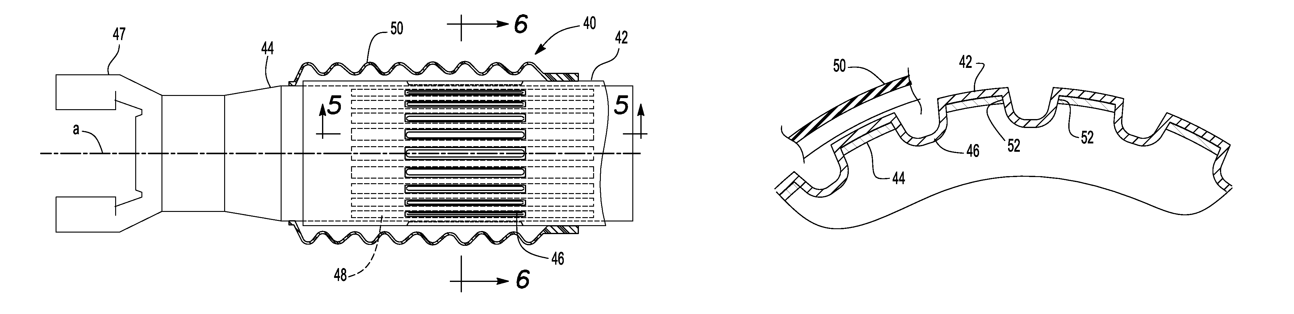
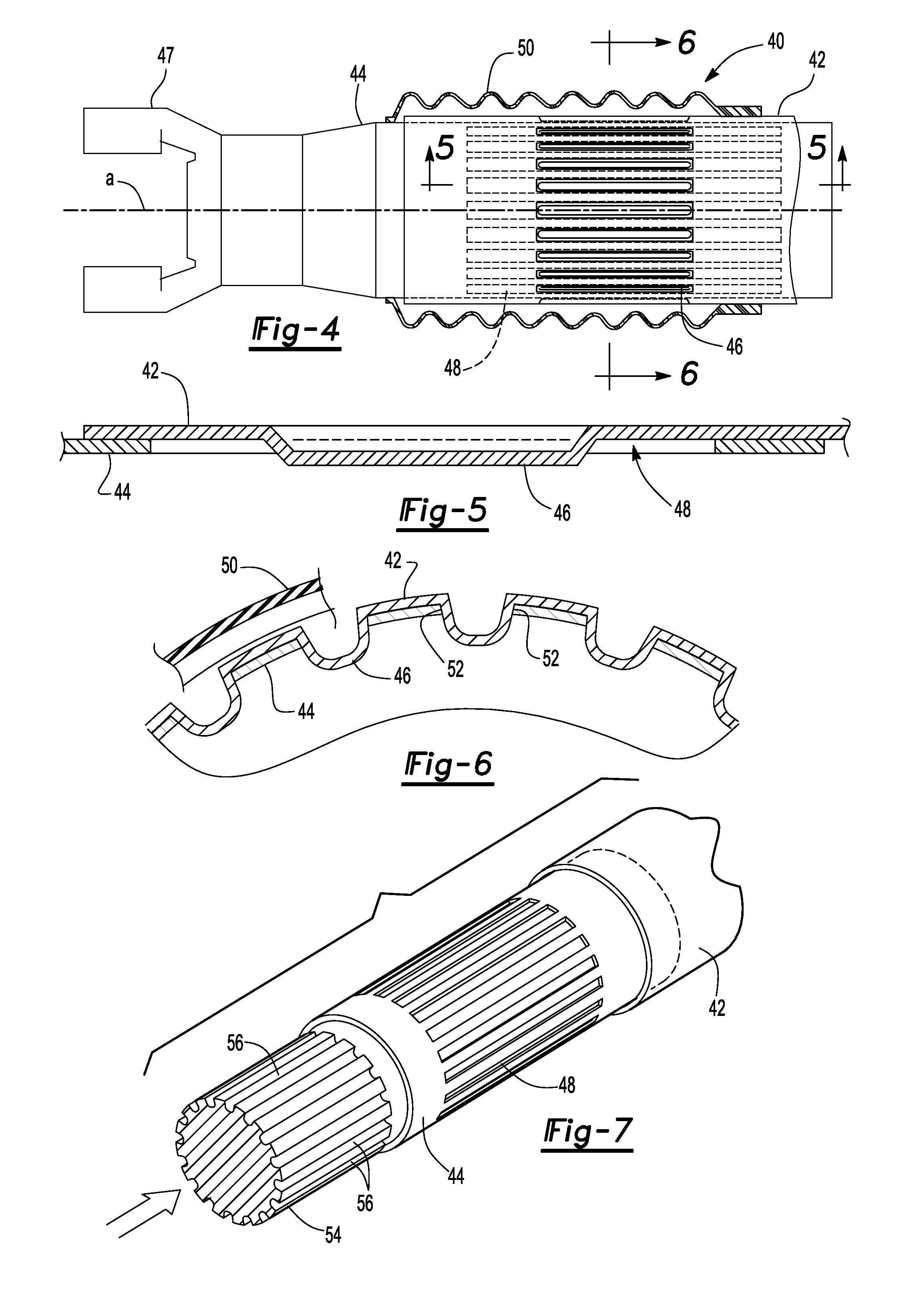
[0020]Referring to FIG. 4, the driveshaft assembly of the present invention is generally shown at 40. The assembly 40 includes a first tubular member 42 and a second tubular member 44. Each of the tubular members 42, 44 are connected to a yoke 47 of a universal joint as is known to those of skill in the art.

[0021]The first tubular member 42 includes a plurality of circumferentially spaced protuberances 46 extending radially inwardly toward axis A of the assembly 40. Each protuberance 46 is received by an aperture 48 defined by the second tubular member 44. Each aperture 48 takes the form of an elongated slot. A plurality of apertures 48 are circumferentially spaced around the second tubular member 44 as best represented in FIG. 4. Each protuberance 46 includes a length that is less than a length of the aperture 48 so that the first tubular member 42 and the second tubular member 44 articulate along axis a when necessary. Therefore, the second tubular member 44 slides inwardly into t...


PUM

PropertyMeasurementUnit
lengthaaaaaaaaaa
widthaaaaaaaaaa
aperture widthaaaaaaaaaa

Abstract

A drive shaft assembly for a vehicle includes a first tubular member and a second tubular member. The second tubular member is mated to the first tubular member. The first tubular member defines a plurality of protuberances and the second tubular member includes a plurality of apertures. Each of the plurality of apertures receives one of the plurality of protuberances substantially affixing the first tubular member to the second tubular member in a circumferential orientation.

Description

BACKGROUND OF THE INVENTION[0001]The present invention relates generally toward a drive shaft of a motor vehicle. More specifically, the present invention relates to a collapsible driveshaft of a motor vehicle.[0002]FIG. 1 shows a power train of a motor vehicle generally at 10. The power train includes a motor 12 that transfers torque to a driveshaft 14. The driveshaft 14 transfers the torque generated by the motor 12 to wheels 18 via differential 16 for driving the motor vehicle. To protect vehicle occupants in the event of a collision, the driveshaft 14 is designed to collapse upon itself if the vehicle length is compressed. When the driveshaft 14 does not collapses upon itself, it is known to encroach the vehicle cabin by bending, or otherwise being displaced in an upward direction.[0003]A prior art driveshaft is generally shown at 20 of FIG. 2. The prior art driveshaft 20 is formed from a first tubular member 22 and a second tubular member 24. First splines 26 are formed on an i...

Claims


Application Information

Patent Timeline
Patent Type & Authority Patents(United States)
IPC IPC(8): F16C3/03
CPCB21D39/032B21D39/04B21D53/88B60K17/22F16D1/104F16D3/06F16C3/02B60Y2306/01Y10T29/49913F16D2001/103F16D2250/0023F16C2326/06
Inventor SZUBA, JOSEPH
Owner SZUBA CONSULTING
Why Eureka
Try Eureka