
Wire filter cage locking mechanism

a technology of locking mechanism and filter cage, which is applied in the direction of separation process, filtration separation, dispersed particle separation, etc., can solve the problems of wire clips not holding the filter cage sections together, and the lower filter cage sections are often damaged

Active Publication Date: 2012-07-24
AIR CURE
View PDF33 Cites 7 Cited by
  • Summary
  • Abstract
  • Description
  • Claims
  • Application Information

AI Technical Summary

Benefits of technology

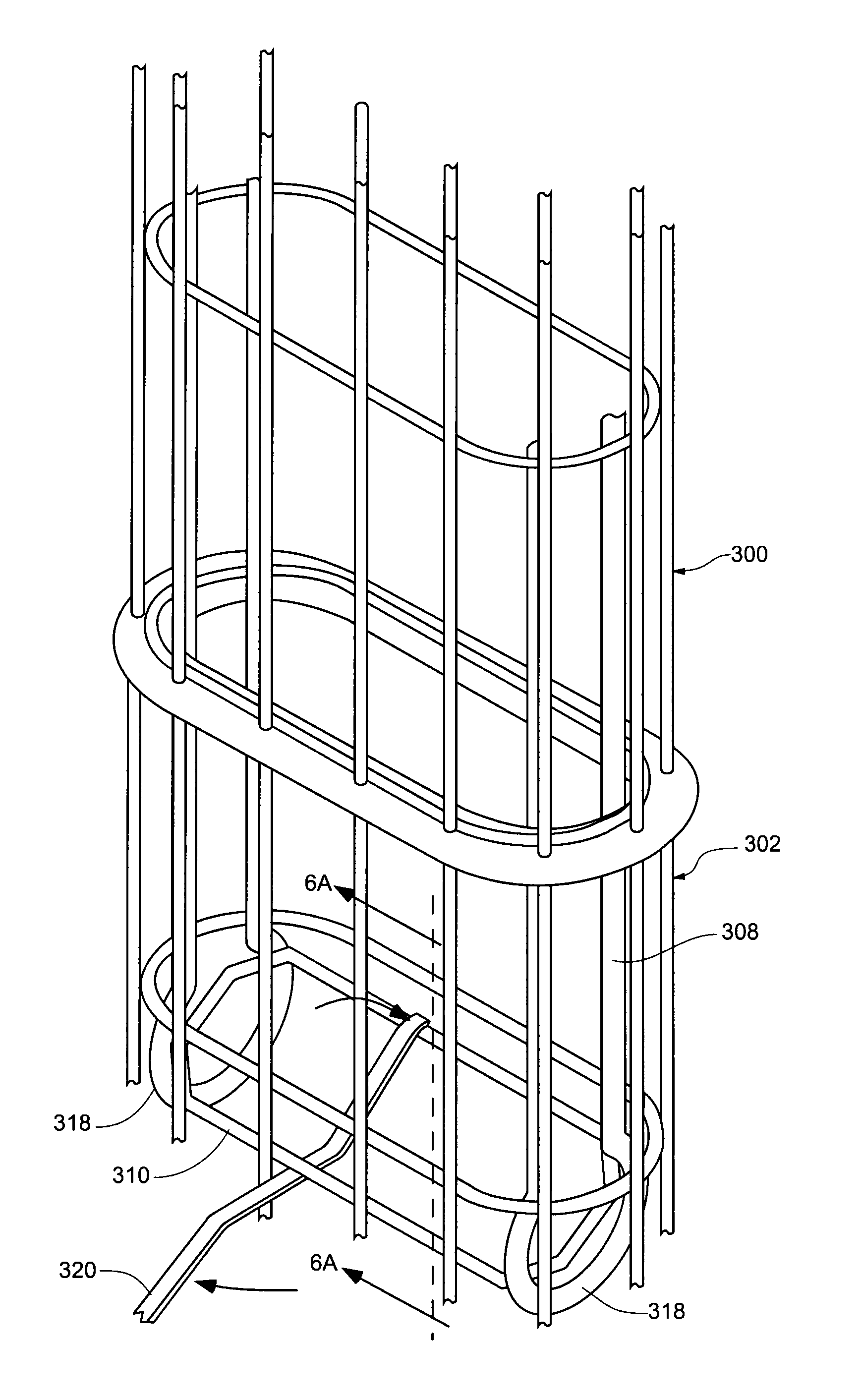
The filter cage lock enhances the structural integrity of the joint, preventing unintended separation and damage, thus extending the lifespan of both filter cages and bags, reducing replacement costs, and ensuring secure connections without exposing sharp edges.

Problems solved by technology

However, under significant longitudinal tension loads the wire clips fail to hold the filter cage sections together.
Further, upon impacting the floor of the dirty air compartment, the lower filter cage sections are often damaged to a degree that makes them unusable.

Method used


Image

  • Wire filter cage locking mechanism
  • Wire filter cage locking mechanism
  • Wire filter cage locking mechanism

Examples


Embodiment Construction

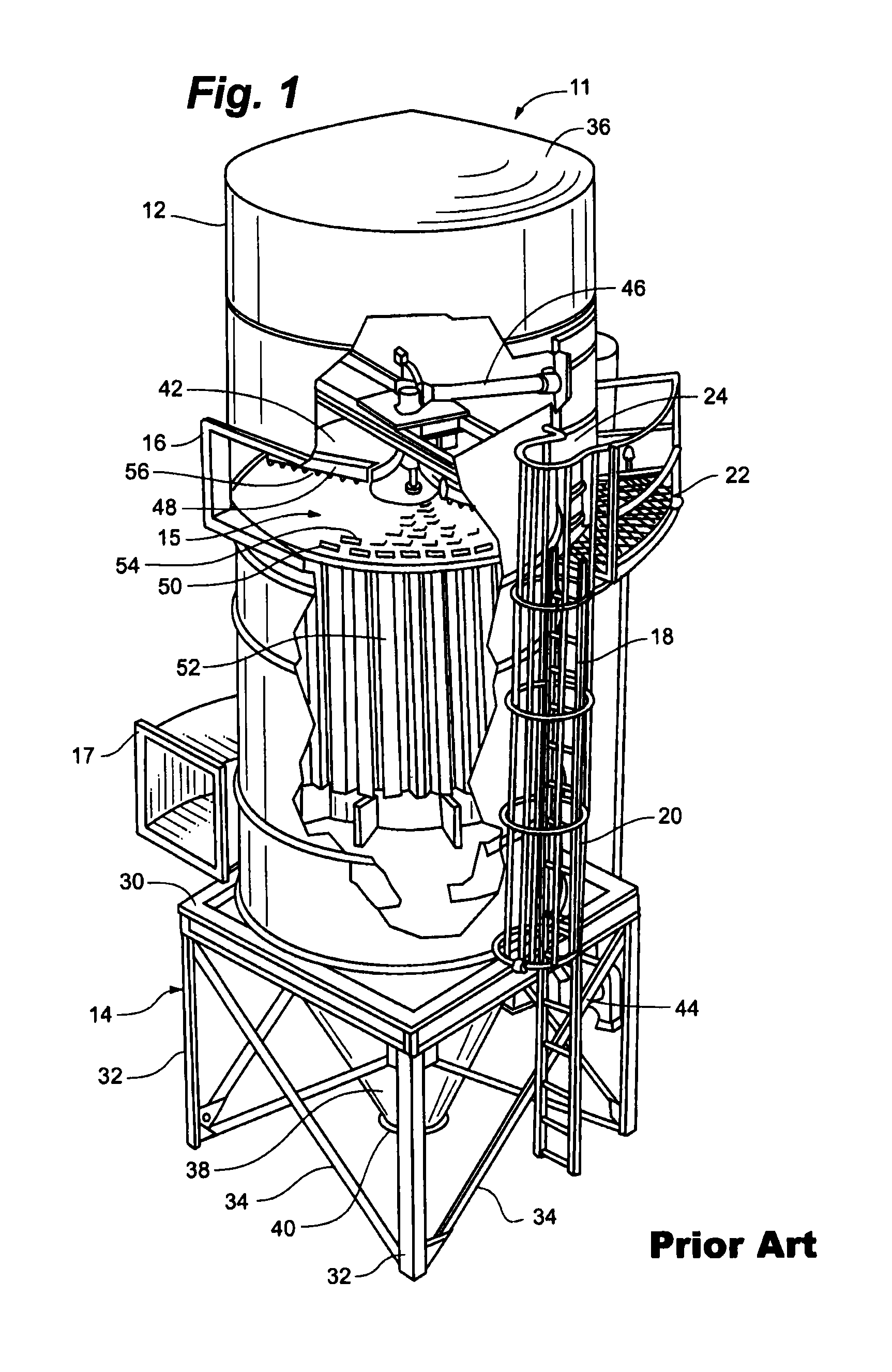
[0059]Referring to FIG. 1, a plurality of filter elements are depicted as installed in an air filtration unit 11. The air filtration unit 11 broadly includes plenum enclosure 12, base frame 14, air filtration assembly 15, filtered exhaust duct 16, and air intake duct 17. Air filtration unit 11 is utilized, for instance, in power or nuclear plants, coal dumping facilities, grain handling facilities and buildings where refining operations may take place. Typical ventilation systems used in these environments may range in height from fifty to one hundred feet. An access ladder 18, surrounded by safety cage 20, leads up to catwalk 22, provides access to plenum enclosure 12 through access door 24. Filtered exhaust duct 16 and air intake duct 17 may be attached to an integral with plenum enclosure 12. Air filtration assembly 15 is positioned within plenum enclosure 12. Plenum enclosure 12 is positioned on base frame 14.

[0060]Base 14 may include frame 30, legs 32, and braces 34. Base 14 ma...


PUM

PropertyMeasurementUnit
lengthsaaaaaaaaaa
heightaaaaaaaaaa
heightaaaaaaaaaa

Abstract

A filter bag support structure, including a first section and a second section. The first section includes a pair of opposed alignment members located partially internal to the first section and extending outwardly away from the first section aligned to insert into the second section. The second section includes at least one annular member. The alignment members are receivable within the second section and have engagement members near a distal end. A locking member is removeably insertable between the opposed alignment members and inhibits the alignment members from flexing inwardly when the locking member is inserted and causes the alignment members to resist being removed from the at least one annular member when a tension load is applied that would tend to separate the first section from the second section to a greater degree than when the locking member is not present.

Description

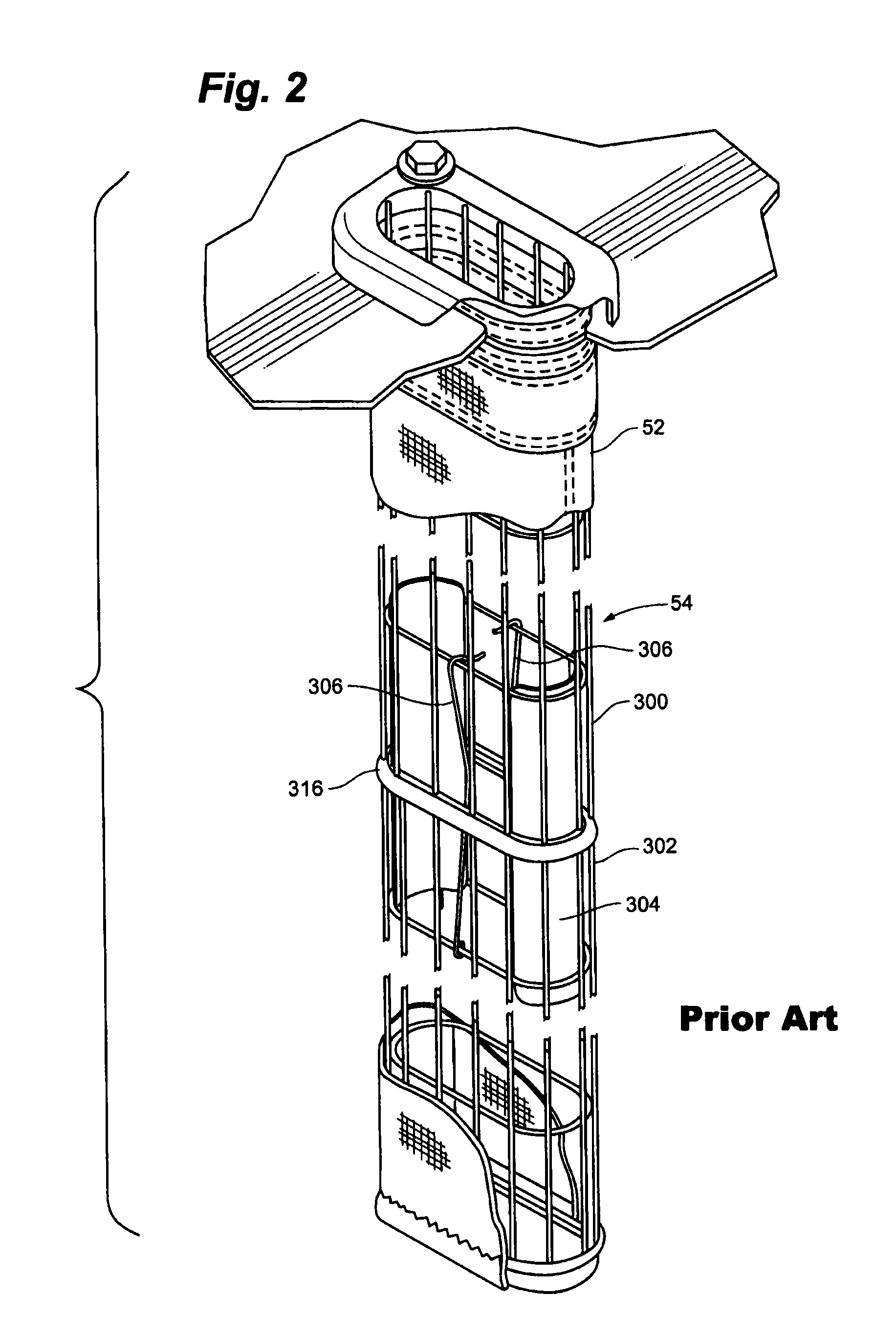
FIELD OF THE INVENTION[0001]The present invention relates to an air filtration system suitable for use within the ventilation system of a building. More particularly, the invention relates to improved filter cages used for supporting elongated filtration bags or socks within such a filtration system and securing filter cage sections together.BACKGROUND OF THE INVENTION[0002]Air filtration systems utilized in large ventilation systems often employ banks of elongated filtration bags or socks supported by wire filter cage assemblies. The filtration bags are positioned over the filter cages and remove particulates from the air circulated through the bag. The wire filter cages support the bags and prevent the bags from collapsing as air is drawn through the bags. Filter media exclude particulates from passing through the bag along with the air, and the particulates accumulate on the outside of the bags as air is drawn through the bag and filter cage combination.[0003]Wire filter cages su...

Claims


Application Information

Patent Timeline
Patent Type & Authority Patents(United States)
IPC IPC(8): B01D46/02
CPCB01D45/02B01D46/06B01D2265/06B01D2275/208
Inventor HARRISUGARGOL, KALPIPKORN, HOWARDJOHNSON, JOHN
Owner AIR CURE
Learn More