Battery-powered occupancy sensor

a battery-powered occupancy sensor and occupancy sensor technology, applied in the direction of electric variable regulation, process and machine control, instruments, etc., can solve the problems of increasing the likelihood that the load control device may not detect the presence of a user, and the control system requires advanced system components and configuration procedures in order to operate properly

Active Publication Date: 2012-07-24
LUTRON TECH CO LLC
View PDF187 Cites 405 Cited by
  • Summary
  • Abstract
  • Description
  • Claims
  • Application Information

AI Technical Summary

Problems solved by technology

However, since the wall-mounted load control devices are mounted to a wall in a standard electrical wallbox (i.e., replacing a standard light switch), the detection of energy by the PIR detector may be hindered due to the direction that the load control device is facing and by obstacles in the space, thus increasing the likelihood that the load control device may not detect the presence of a user.
However, these prior art lighting control systems require advanced system components and configuration procedures in order to operate properly.

Method used


Image

  • Battery-powered occupancy sensor
  • Battery-powered occupancy sensor
  • Battery-powered occupancy sensor

Examples


first embodiment

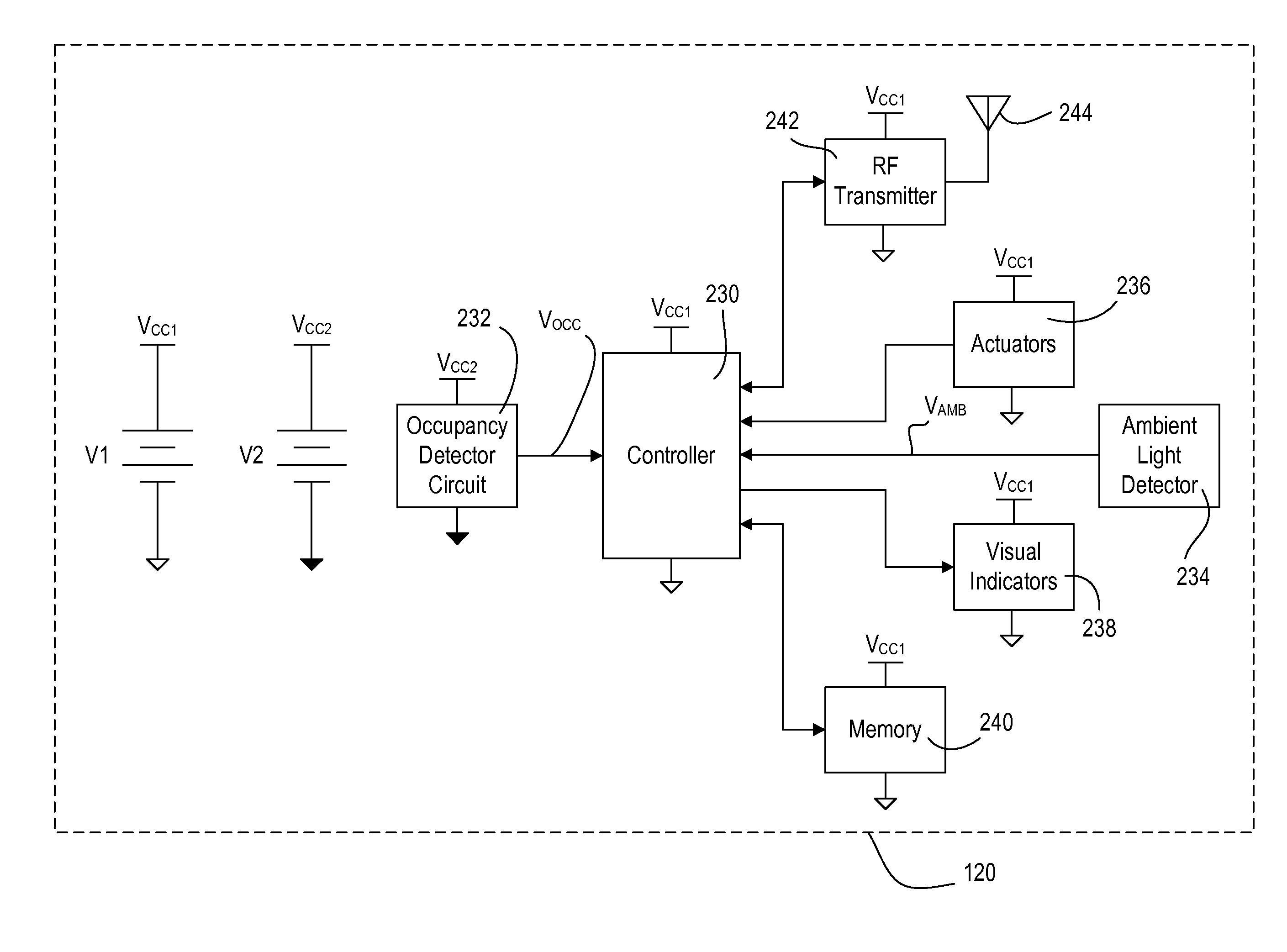
[0058]According to the present invention, the occupancy sensors 120 are each operable to store in a memory 240 the values of the various operating characteristics of the lighting control system 100, e.g., the occupancy voltage threshold, the ambient light level threshold, and the occupancy sensor timeout period TTIMEOUT. The memory 240 may be implemented as an external integrated circuit (IC) or as an internal circuit of the controller 230. To adjust the values of the operating characteristics, the user must access the occupancy sensor 120 to actuate the actuators 236. The occupancy sensors 120 use the operating characteristics to change between the occupied state and the vacant state as will be described in greater detail below. The occupancy sensors 120 also store the serial number in the memory 240. The serial number may be programmed into the memory 240, for example, during manufacture of the occupancy sensor 120.

[0059]The remote occupancy sensor 120 further comprises an RF tran...

second embodiment

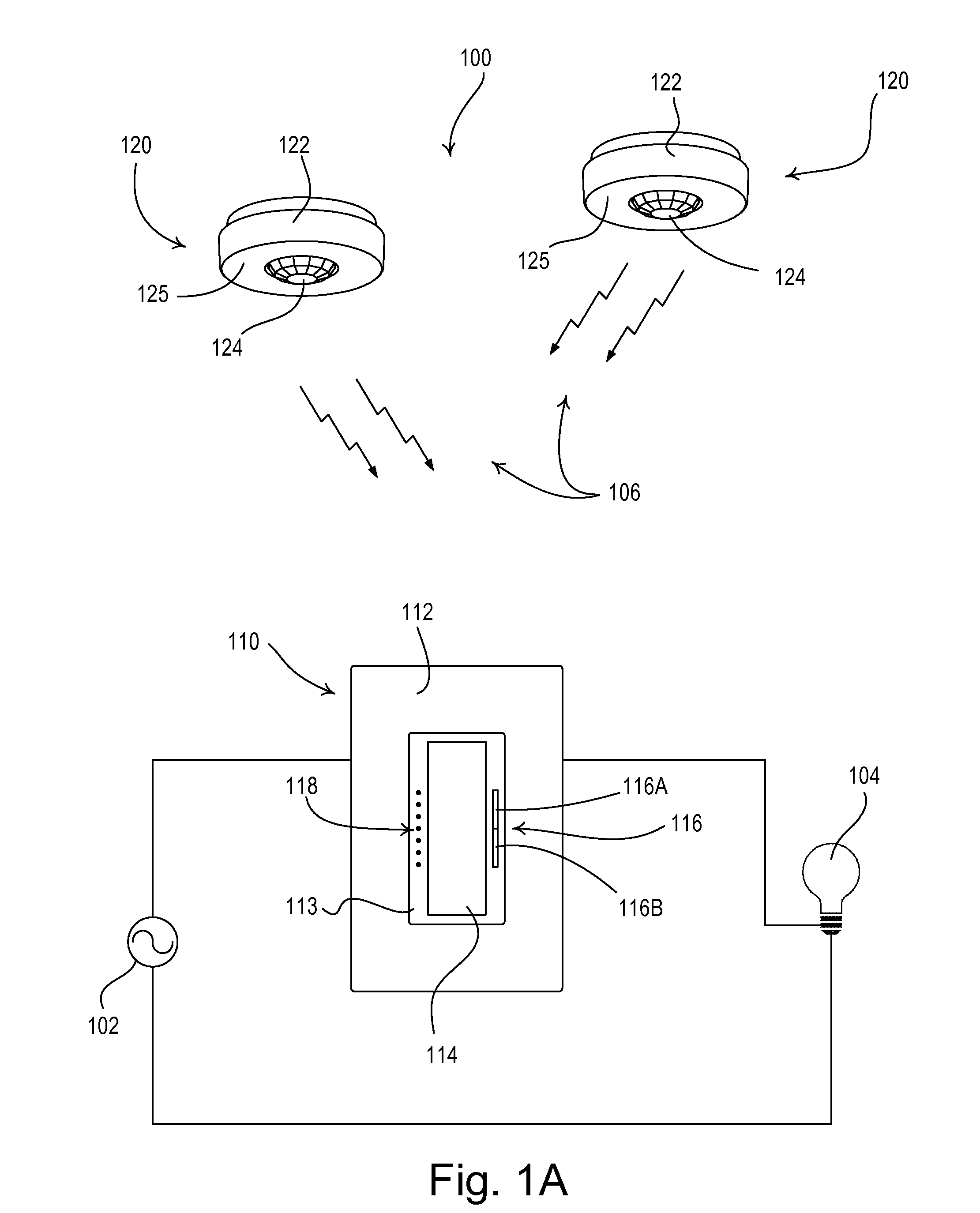
[0093]According to the present invention, the occupancy sensor 120 operates in a low-battery mode when the magnitude of the first battery voltage VCC1 drops below the low-battery voltage threshold VLOW. In the low-battery mode, the controller 230 halts the normal operation of the occupancy sensor 120 to conserve battery power. Specifically, the controller 230 does not transmit the occupied-take-action or occupied-no-action commands in response to determining that the room has become occupied, or transmit the vacant command in response to determining at the room has become vacant. In addition, the occupancy sensor 120 provides a visual indication of the low-battery condition by operating to illuminate the lens 124 only when the room first becomes occupied when in the low-battery mode. Accordingly, the lighting load 104 will not turn on, but the lens 124 of the occupancy sensor 120 will be illuminated only when an occupant first enters the space, thus notifying the occupant that the b...

third embodiment

[0098]According to the present invention, the dimmer switch 110 is operable to store in the memory 216 the values of the various operating characteristics of the lighting control system 100, e.g., the occupancy voltage threshold, the ambient light level threshold, and the occupancy sensor timeout period TTIMEOUT. The dimmer switch 110 may provide, for example, an advanced programming mode, such that the values of the operating characteristics may be adjusted in response to actuations of the toggle actuator 114 and the intensity adjustment actuator 116. An advanced programming mode is described in greater detail in U.S. Pat. No. 7,190,125, issued Mar. 13, 2007, entitled PROGRAMMABLE WALLBOX DIMMER, the entire disclosure of which is hereby incorporated by reference. Since the user does not need to access the occupancy sensors 120 (which may be mounted to a ceiling) to adjust the operating characteristics, the use of the toggle actuator 114 and the intensity adjustment actuator 116 of ...


PUM


Abstract

A load control system comprises a load control device and a battery-powered occupancy sensor, which transmits a first wireless signal to the load control device in response to detecting the presence of an occupant in a space. The load control system further comprises a visual indicator for providing a visual indication when the magnitude of a battery voltage of a battery of the occupancy sensor has dropped below a predetermined low-battery voltage threshold. The occupancy sensor may comprise the visual indicator, such that the visual indicator is illuminated when the occupancy detects the presence of the occupant in the space and the magnitude of the battery voltage is less than the predetermined threshold. Alternatively, the load control device may comprise the visual indicator, such that the visual indicator is illuminated in response to receiving a second wireless signal, which is transmitting by the occupancy sensor when the magnitude of the battery voltage is less than the predetermined threshold.

Description

RELATED APPLICATIONS[0001]This application is a continuation-in-part of commonly-assigned, co-pending U.S. patent application Ser. No. 12 / 203,500, filed Sep. 3, 2008, entitled BATTERY-POWERED OCCUPANCY SENSOR, the entire disclosure of which is hereby incorporated by reference.BACKGROUND OF THE INVENTION[0002]1. Field of the Invention[0003]The present invention relates to occupancy and vacancy sensors for detecting an occupancy or a vacancy in a space, and more particularly, to a wireless load control system including a plurality of battery-powered occupancy or vacancy sensors for detecting an occupancy or a vacancy in a space, and a load control device for controlling the amount of power delivered to an electrical load in response to the occupancy or vacancy sensors.[0004]2. Description of the Related Art[0005]Occupancy and vacancy sensors are often used to detect occupancy and / or vacancy conditions in a space in order to control an electrical load, such as, for example, a lighting ...

Claims


Application Information

Patent Timeline
Patent Type & Authority Patents(United States)
IPC IPC(8): G08B1/08
CPCG08B13/191G08B29/181H05B37/0227H05B37/0272Y02B20/44H05B47/19Y02B20/40H05B47/115
Inventor BLAKELEY, MATTHEW ROBERTSTEINER, JAMES P.SCHREMS, ADAM J.
Owner LUTRON TECH CO LLC
Why Eureka
Try Eureka