Transmission

a technology for transmission and shaft, applied in the direction of gearing details, transportation and packaging, gearing, etc., can solve the problems of cost-cutting of transmission, and achieve the effect of reducing the size of the transmission in an axial direction of the shaft, and reducing the number of necessary components

Active Publication Date: 2012-08-07
HONDA MOTOR CO LTD
View PDF10 Cites 7 Cited by
  • Summary
  • Abstract
  • Description
  • Claims
  • Application Information

AI Technical Summary

Benefits of technology

[0007]With this arranged, since the first mounting portion and the second mounting portion overlap each other in an axial direction thereof (which is parallel to the axis of the shaft), the fixed transmission part and the movable transmission part come close to each other and, hence, a size of the transmission in an axial direction of the shaft can be reduced.
[0008]Furthermore, by virtue of the single seal member provided between the first and second connecting portions, it is possible to reduce a number of necessary components of the transmission as compared to the conventional transmission which requires two seal members each disposed between the shaft and a respective one of the fixed and movable transmission units. Reduction in the number of necessary components leads to cost-cutting of the transmission.

Problems solved by technology

Reduction in the number of necessary components leads to cost-cutting of the transmission.

Method used


Image

  • Transmission
  • Transmission
  • Transmission

Examples


Embodiment Construction

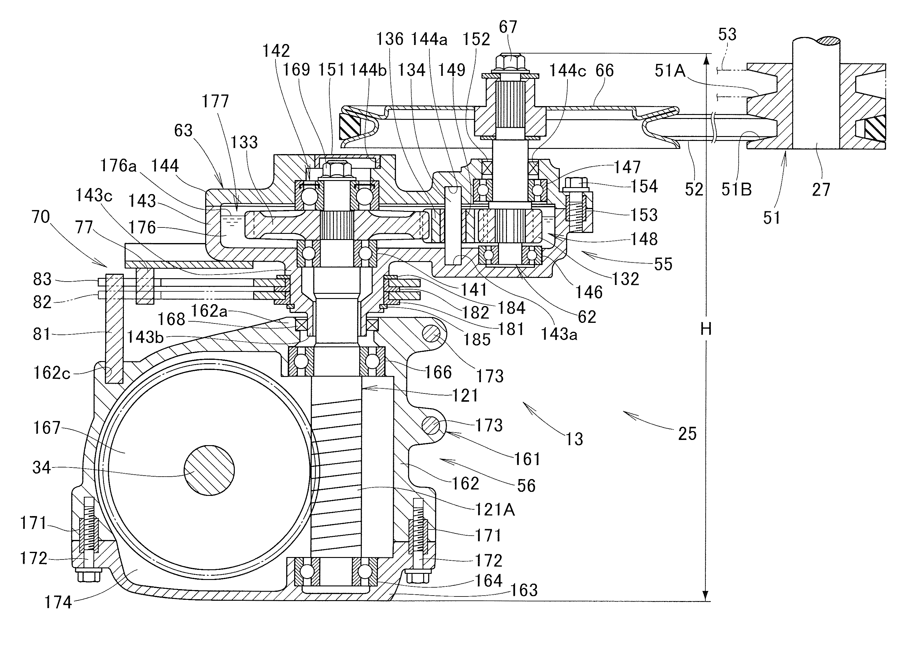
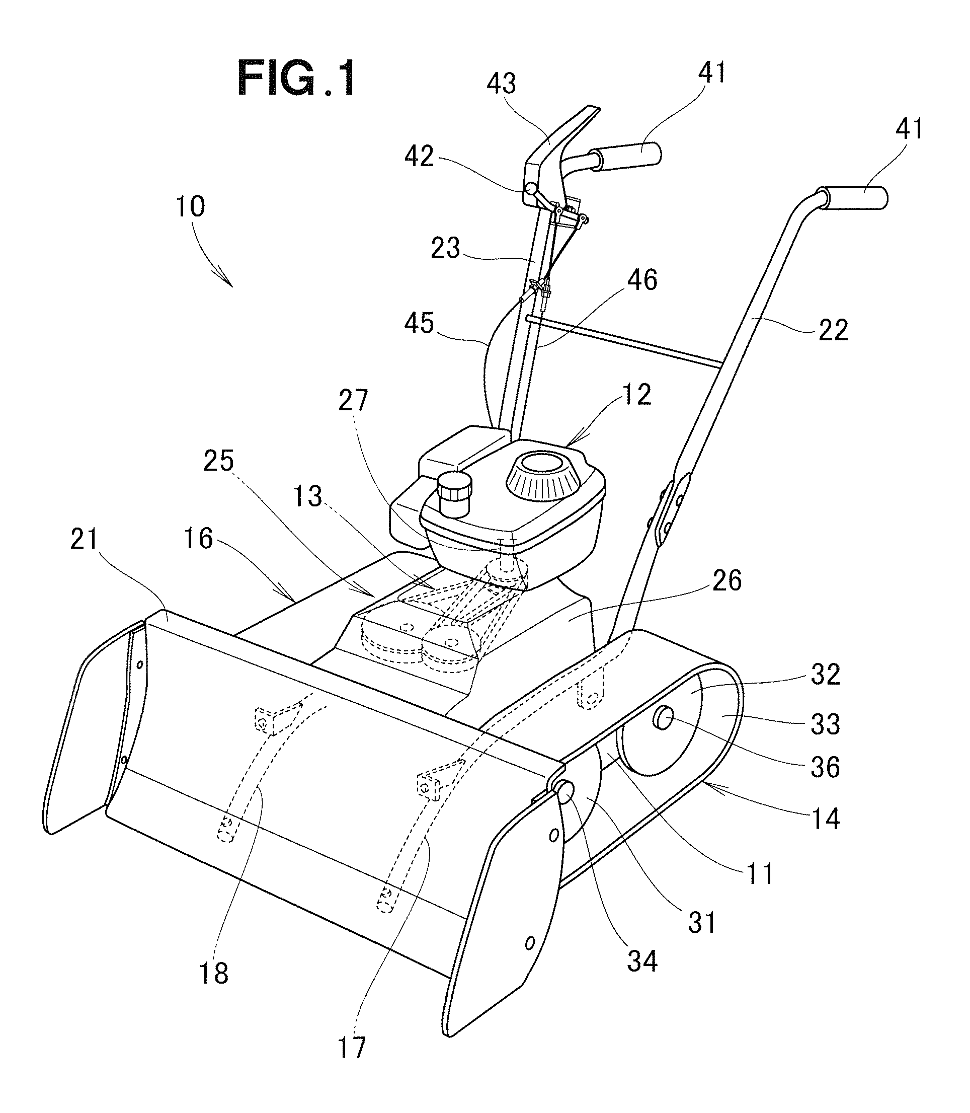
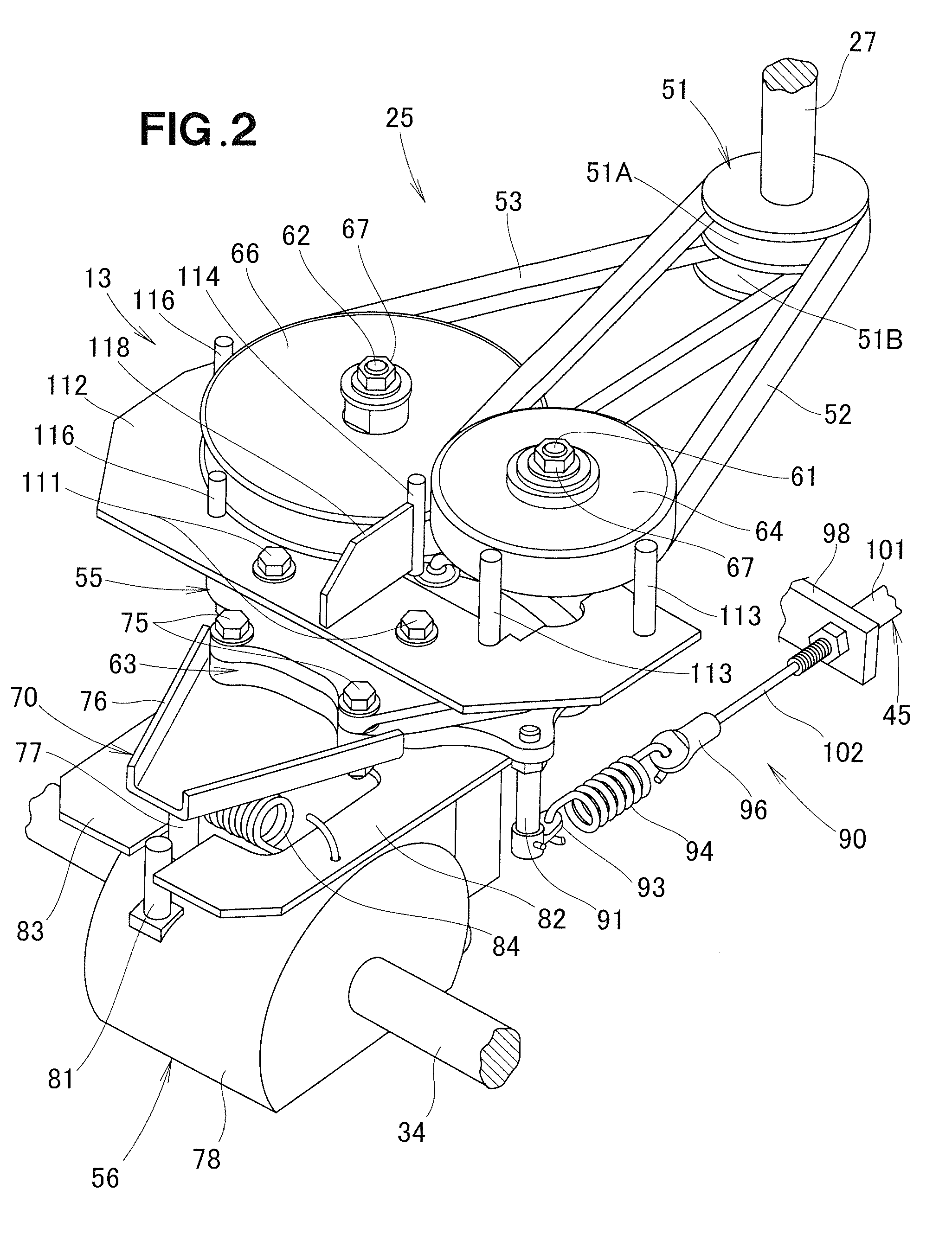
[0027]Referring now to the drawings and FIG. 1 in particular, there is shown a small-sized snow removing machine 10 incorporating therein a transmission 13 according to one preferred embodiment of the present invention. The snow removing machine 10 generally comprises a body 11, an engine 12 mounted on the body 11, the transmission 13 mounted on the body 11 for transmitting power from the engine 12 to a pair of (left and right) crawler traveling units 14 and 16, a pair of (left and right) swing pipes 17 and 18 pivotally connected to the body 11, a snow removing blade 21 connected to front end portions of the respective swing pipes 17, 18, and a pair of (left and right) handlebars 22 and 23 connected to rear ends of the respective swing pipes 17, 18 and extending upwardly rearwards of the body 11. The transmission 13 is incorporated in a power transmission device 25 which is configured to transmit power from the engine 12 to the left and right crawler traveling units 14, 16. The tran...


PUM


Abstract

A transmission has a movable transmission part movably connected to a fixed transmission part via a shaft to undergo pivotal movement relative to the fixed transmission part about an axis of the shaft. Each of the transmission parts has a hollow cylindrical connecting portion through which the shaft extends. One of the connecting portion of the movable transmission part and the connecting portion of the fixed transmission part is received in the other of the connecting portions with a single seal member disposed therebetween so that an internal space of the fixed transmission part and an internal space of the movable transmission part communicate with each other to thereby form a single hermetically-sealed space for holding therein a lubricating oil.

Description

FIELD OF THE INVENTION[0001]The present invention relates generally to a transmission, and more particularly to a composite transmission having a fixed transmission part and a movable transmission part movably connected to the fixed transmission part via a shaft to undergo pivotal movement relative to the fixed part about an axis of the shaft.BACKGROUND OF THE INVENTION[0002]Conventional transmissions are configured to receive power from an engine via an input shaft thereof and transmit the engine power from an output shaft thereof to a crawler traveling unit for driving the crawler traveling unit. A typical example of such conventional transmissions is disclosed in Japanese Patent Laid-open Publication (JP-A) No. 63-223207.[0003]The disclosed transmission has an input shaft adapted to be connected to an engine, a series of shift gears connected in driven relation to the input shaft, an output shaft connected in driven relation to a final shift gear of the series of shift gears, a c...

Claims


Application Information

Patent Timeline
Patent Type & Authority Patents(United States)
IPC IPC(8): F16H1/20F16H9/00F16H57/02F16H37/06F16H57/023F16H57/027F16H57/029F16H57/04
CPCF16H57/029F16H57/039F16H9/04F16H2057/02013F16H2057/02056F16H2057/02086Y10T74/19819Y10T74/19693Y10T74/20177Y10T74/19084Y10T74/2186Y10T74/19828F16H2057/02095
Inventor KOHIGASHI, KENTAISHIKAWA, TOMOAKIMIYAHARA, KAZUYOSHI
Owner HONDA MOTOR CO LTD
Why Eureka
Try Eureka