Separator and separator cartridge
- Summary
- Abstract
- Description
- Claims
- Application Information
AI Technical Summary
Benefits of technology
Problems solved by technology
Method used
Image

Examples
first embodiment
1. First Embodiment
1.1. Configuration of Separator
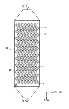
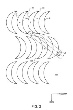
[0061]FIG. 1 is a plan view schematically illustrating a separator 100 according to an embodiment of the present invention. FIG. 2 is an enlarged view schematically illustrating a plane pattern of a plurality of columnar members 10 provided for channels 50 shown in FIG. 1. FIG. 3 is a perspective view schematically illustrating the columnar members 10 provided for the channels 50 shown in FIG. 1. FIG. 4 is a cross sectional view schematically illustrating the channels 50 shown in FIG. 1 (a cross section at Y-Y perpendicular to the plane of the paper). FIG. 5 is a diagram representing a method for separating a separation target using the channels 50 shown in FIG. 1.
[0062]As illustrated in FIG. 1, the separator 100 according to the embodiment of the invention includes the channels 50 provided with an inlet 30 and an outlet 40. A separation target liquid with a potential separation target is introduced through the inlet 30, and discharg...
second embodiment
2. Second Embodiment
[0105]FIG. 9 is a diagram schematically illustrating a separator system (cancer cell removing system) 1000 according to an embodiment of the present invention. The present embodiment will be described through the case where the separator system 1000 is used to remove cancer cells. However, as noted in First Embodiment, the separator system 1000 according to the present embodiment can be used to separate separation targets other than cancer cells.
[0106]As illustrated in FIG. 9, the separator system 1000 according to the present embodiment includes the separator 100 of First Embodiment, and a controller 27. The separator 100 removes cancer cells from the bodily fluid collected from a patient 300. The separator system 1000 further includes a tube 21 used for the transfer of the bodily fluid collected from the patient 300, a pump 23 that drives the transfer of the bodily fluid through the tube 21, and pressure monitoring units 25 and 26 that monitor the pressure of t...
PUM
| Property | Measurement | Unit |
|---|---|---|
| height | aaaaa | aaaaa |
| height | aaaaa | aaaaa |
| diameters | aaaaa | aaaaa |
Abstract
Description
Claims
Application Information