Gear module

a gear module and gear technology, applied in the direction of gearing details, gearing, transportation and packaging, etc., can solve the problems of laborious removal of the gear module for maintenance or the incorporation of this gear module into an existing driv

Active Publication Date: 2012-08-07
DTI GRP BV
View PDF16 Cites 6 Cited by
  • Summary
  • Abstract
  • Description
  • Claims
  • Application Information

AI Technical Summary

Benefits of technology

[0009]An objective of the invention is to provide a gear module which can be easily incorporated in and removed from a drive. For this purpose, the drive according to the invention is characterized in that the gear module comprises a connecting gear wheel that can be made to engage the first gear wheel of the drive and which is disconnectably connected to the second rotation body via second connection devices. A very compact and simple clutch is obtained with the drive by allowing the connecting gear wheel to work directly with the first gear wheel and not connecting it to the first gear wheel.
[0013]An embodiment of the gear module according to the invention is characterized in that the gear module comprises activation devices for the operation of the clutch, which activation devices are installed concentrically inside the connecting gear wheel. This limits the axial room needed by the gear module.
[0021]Moreover, the brake shoes on the side facing the brake disc are preferably hardened or provided with a durable coating, or between the brake shoes and the brake disc there are hard intermediate plates in order to be more durable.
[0024]Still a further embodiment of the gear module according to the invention is characterized in that the brake is such that it is disengaged when not activated. This means that no activation power is needed for the brake when the vehicle is being driven in gear so that there are also no activation losses.
[0027]Moreover, the brake is preferably a wet-plate brake or a dry-plate brake. This means that a radial seal between the third rotation body and a section of the brake housing is saved.
[0037]The activation devices are preferably fastened to the connecting element. The activation devices in this case rotate together with the connecting element so that two extra sealing rings are needed. However, this saves a radial seal between the first rotation body and the housing, and a thrust bearing between the piston of the activation devices and the connecting element.

Problems solved by technology

The disadvantage of this known gear module is that the incorporation of this gear module in an existing drive or the removal of the gear module for maintenance is very laborious.

Method used


Image

  • Gear module
  • Gear module
  • Gear module

Examples


Embodiment Construction

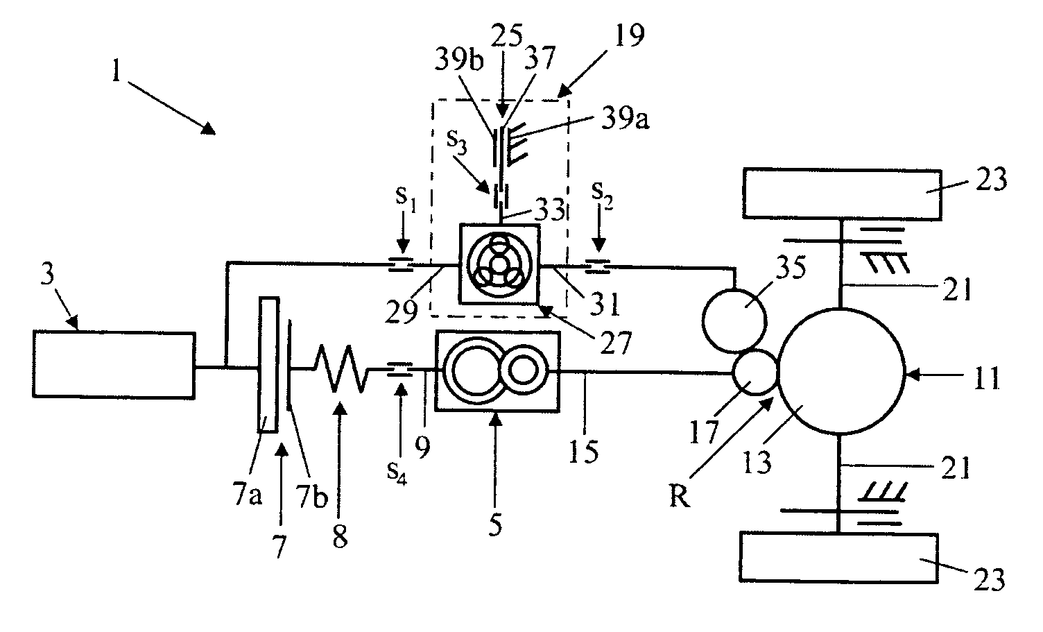
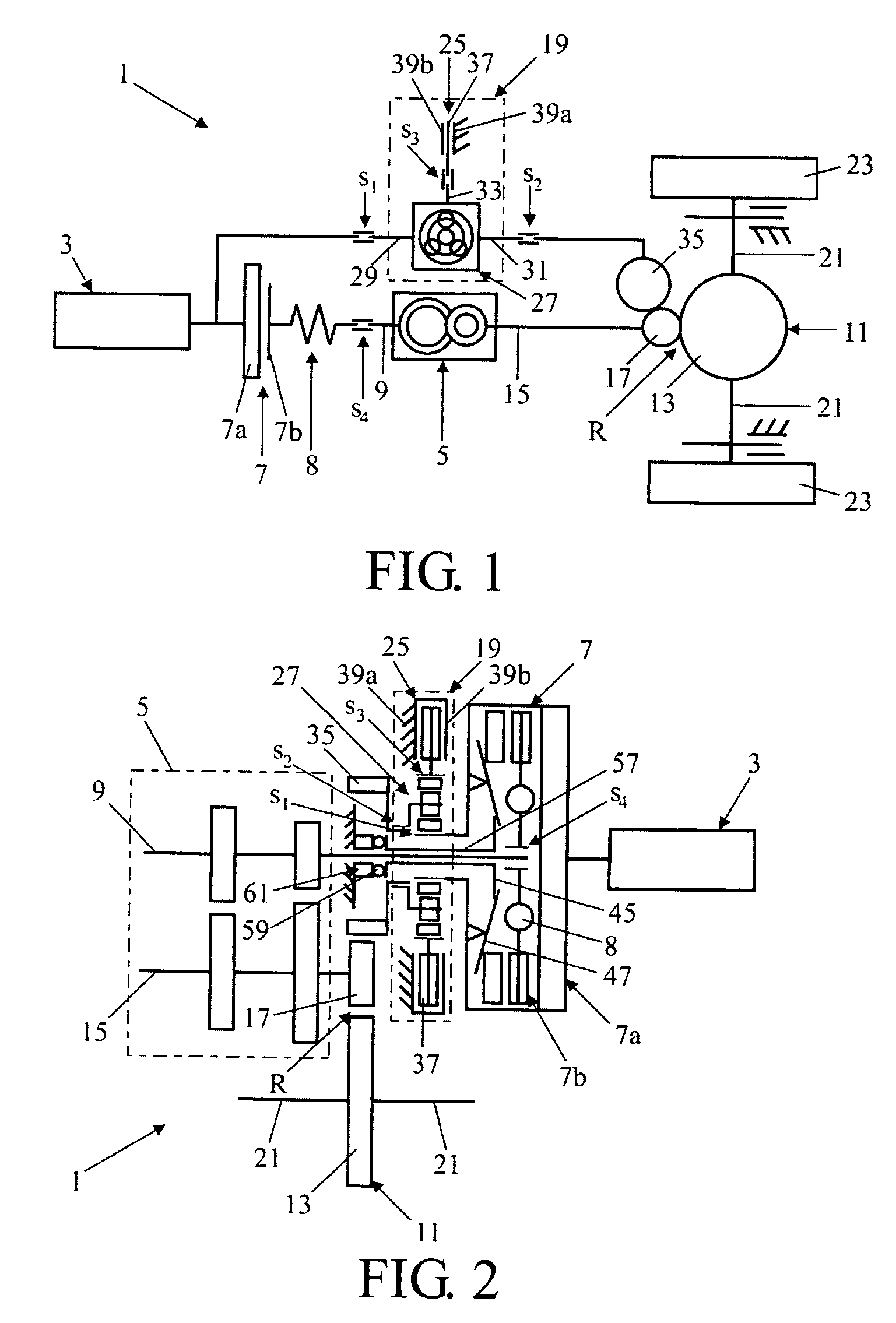
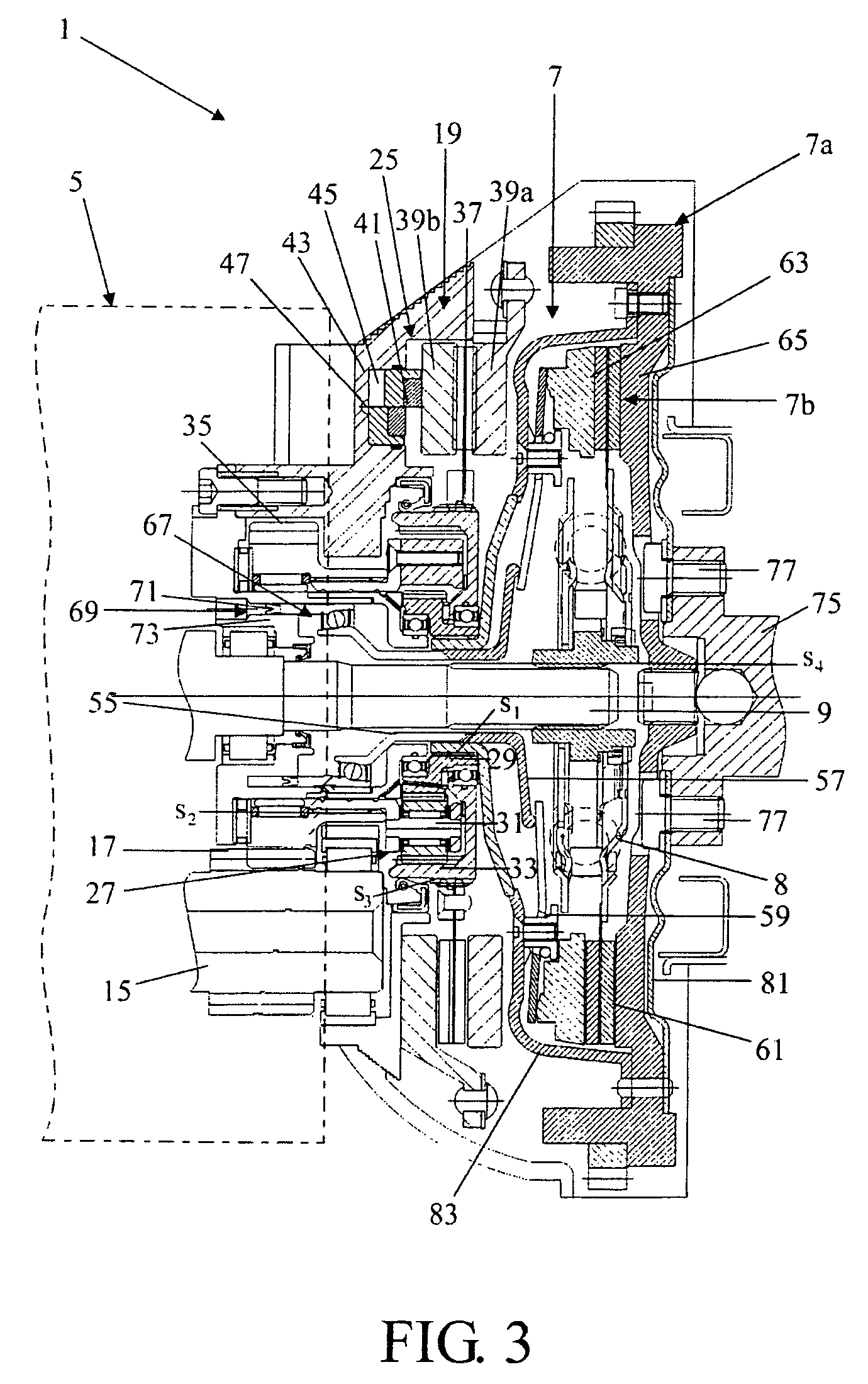
[0057]FIGS. 1, 2 and 3 show an embodiment of a vehicle drive provided with the gear module according to the invention as a diagram and in concrete form respectively. The drive 1 has a drive source 3 and an automatic manual gearbox 5 connected to it. The automatic gearbox 5 is adapted to be operably engaged with the drive source 3.

[0058]A friction clutch 7 is positioned between the drive source and the gearbox, of which a first clutch part 7a is connected to the drive source and the second clutch part 7b is connected via splines s4 to an input shaft 9 of the gearbox. There is a torsion spring 8 between the second clutch half 7b and the splines to suppress vibrations from the drive source 3. The drive also has a differential 11, which engages a first gear wheel 17 on the gearbox output shaft 15 with a gear wheel 13, which gear wheels 13 and 17 form an end reduction R of the drive. The differential 11 is connected via drive shafts 21 to the vehicle wheels 23. In addition, the drive has...


PUM


Abstract

A drive has a drive source connected with an automatic manual gearbox. A friction clutch is positioned between the drive source and the gearbox. The drive also has a differential, which with a gear wheel engages a first gear wheel on the gearbox output shaft, as well as a gear module to change the transmission in the gear without interrupting the drive. The gear module has a brake and a bypass transmission with three rotation bodies of which a first rotation body is connected to the first clutch part, a second rotation body is connected to a connecting gear wheel, which engages the first gear wheel, and the third rotation body is connected to the brake. The connections of the rotation bodies to the parts stated and respectively of the drive are made in this as splines.

Description

BACKGROUND OF THE INVENTION[0001]1. Field of the Invention[0002]The invention relates to a gear module usable in a drive.[0003]2. Description of Related Art[0004]A prior art gear module is shown in the international patent application WO 2004 / 000314 A1. Using this known gear module in a drive as described above enables the transmission in the gear to be changed without interrupting the drive line between the drive source and the driven wheels. The disadvantage of this known gear module is that the incorporation of this gear module in an existing drive or the removal of the gear module for maintenance is very laborious.SUMMARY OF THE INVENTION[0005]The present invention teaches certain benefits in construction and use which give rise to the objectives described below.[0006]The present invention provides a drive that includes a drive source and an automatic gearbox connected to it with an input and an output shaft. A friction clutch is present between the drive source and the gearbox ...

Claims


Application Information

Patent Timeline
Patent Type & Authority Patents(United States)
IPC IPC(8): F16H37/08F16D65/18
CPCF16H3/006F16H3/12Y10T74/19637F16H2306/54F16H2061/0425F16H3/00B60K17/06B60K17/04
Inventor VAN DRUTEN, MARIE ROELLVROEMEN, BAS GERARDSERRARENS, ALEXANDER FRANCISCUS ANITA
Owner DTI GRP BV
Why Eureka
Try Eureka