

Information input output method using dot pattern
a technology of information input and output method, which is applied in the direction of digitally marking record carriers, visual presentation using printers, instruments, etc., can solve the problems of obstructing the view, unable to arrange many bar codes in a limited layout space with each bar code placed, and dot print errors, etc., to ensure the security of each other.
- Summary
- Abstract
- Description
- Claims
- Application Information
AI Technical Summary
Benefits of technology
Problems solved by technology
Method used
Image

Examples
Embodiment Construction
[0001]1. Technical Field of the Invention
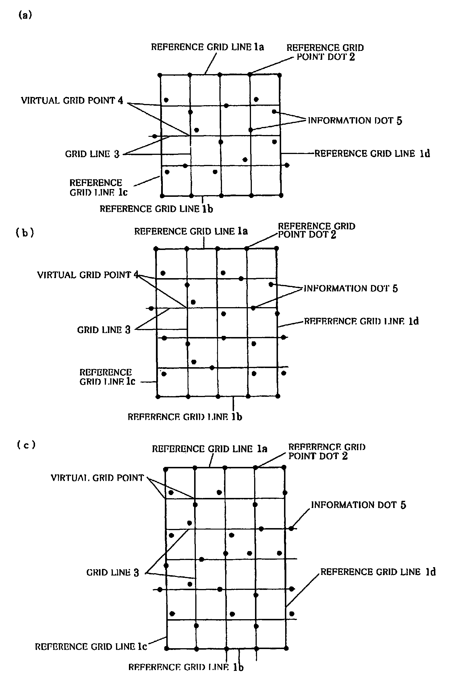
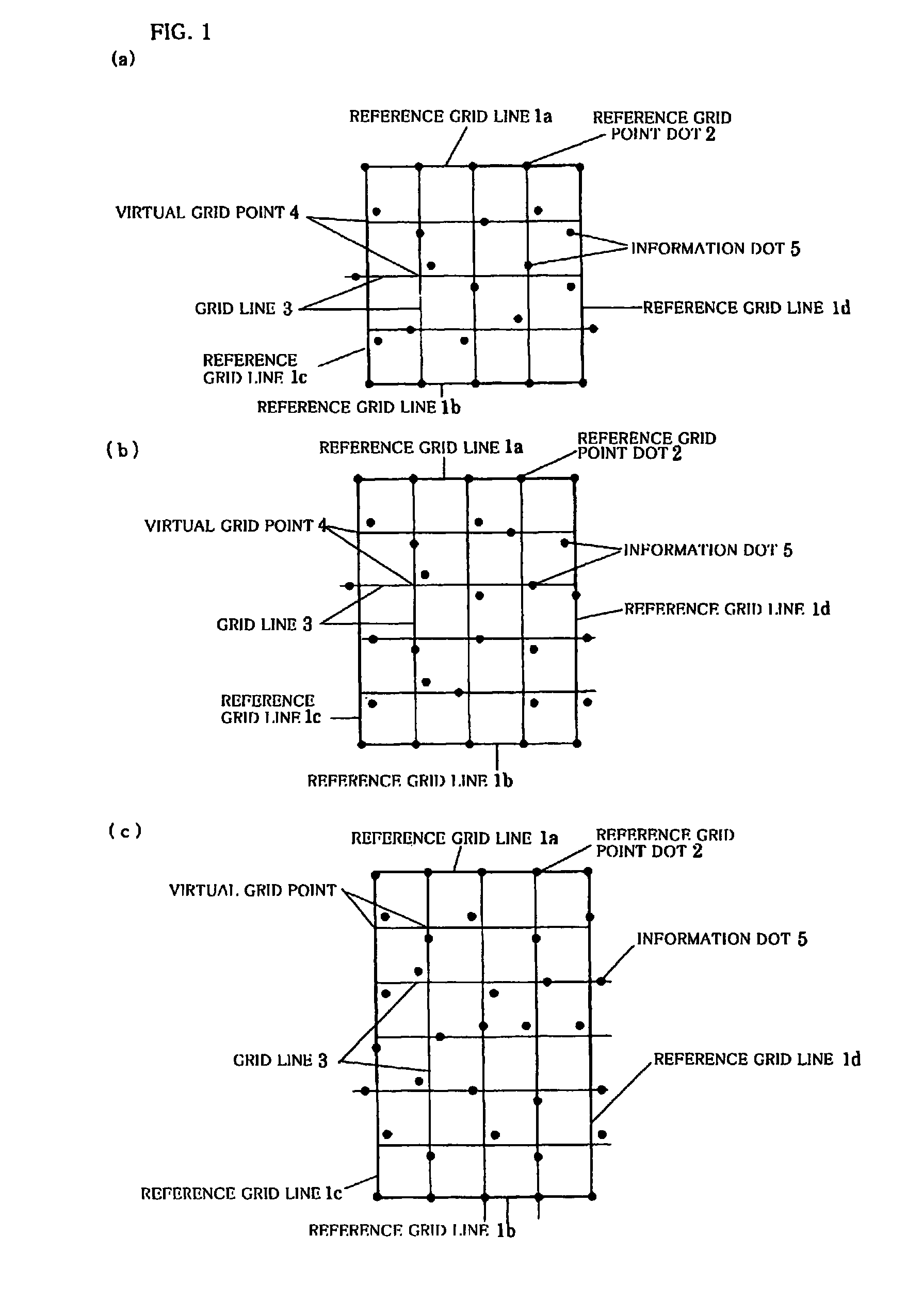
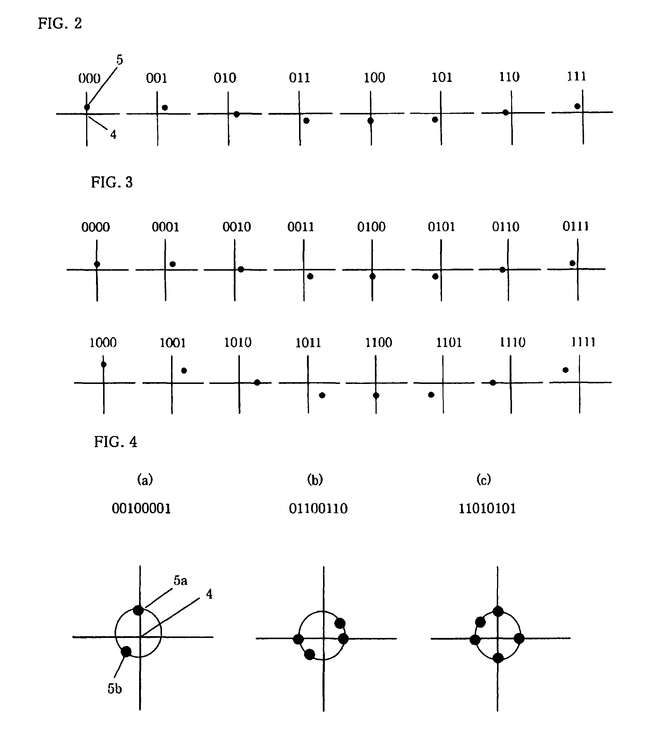
[0002]The present invention relates to an information input output method using a dot pattern for inputting and outputting various information and programs by optically scanning dot pattern information formed on a printed material and the like.
[0003]2. Background Art
[0004]There has been proposed an information input output method for outputting audio information and the like by scanning a bar code printed on a printed material and the like. For example, a method has been proposed to store information corresponding to a given key in a storage means, and retrieve the information corresponding to the key scanned by a bar code reader. In addition, a technique has been proposed to generate a dot pattern in which fine dots are arranged based on a predetermined rule to output many information and programs, use a camera to scan the dot pattern printed on a printed material into image data, and digitize the data to output audio information.
[0005]Howev...
PUM
 Abstract
Description
Claims
Application Information