Dryer with recirculated air proportion and method for its operation

a technology of recirculated air and dryer, which is applied in the direction of lighting and heating apparatus, separation processes, furnaces, etc., can solve the problems of increased large amount of lint originating from the dryer in the drying chamber can reach the heater, and increase the risk of burn marks and fire hazards. , to achieve the effect of reducing the energy required for drying, reducing the degree of dryness of the articles to be dried, and reducing the heating outpu

Inactive Publication Date: 2012-08-14
BOSCH SIEMENS HAUSGERATE GMBH
View PDF31 Cites 64 Cited by
  • Summary
  • Abstract
  • Description
  • Claims
  • Application Information

AI Technical Summary

Benefits of technology

[0013]An object of the present invention is to provide a vented dryer having high energy efficiency which uses a proportion of recirculated air and in which the above-described disadvantages caused by lint originating from the drying chamber can be overcome.
[0018]Suitable in particular as a reservoir for rinsing liquid is a condensate container or a part of a condensate container. Preferably, the reservoir can accommodate condensate accumulating in a condensate tray of a condenser dryer. In this way it is possible without great additional overhead in terms of apparatus, essentially using only a condensate pump and condensate tray usually present in any case in a condenser dryer, to perform cleaning of the lint filter in the recirculated air duct. The rinsing liquid can thus contain or consist of condensate. If necessary cleaning agents can be added to the rinsing liquid.
[0036]To allow better control of the proportions of recirculated air and exhaust air in the dryer according to the invention, there is preferably disposed in the recirculated air duct a first controllable closing device, for example a damper, which can be fully or partially opened or closed. It is likewise preferred that a second controllable closing device is disposed in the supply air duct.
[0044]Since the energy required for drying decreases as the degree of dryness of the articles to be dried in the dryer increases, it is beneficial to regulate the heater accordingly, in other words to reduce its heating output as the degree of dryness increases.
[0045]The dryer according to an exemplary embodiment of the invention has the advantage that operating reliability is substantially increased while energy efficiency in recirculated air operation is improved. The cleaning of the lint filter can be accomplished in a simple and efficient manner. Furthermore condensate accumulating in the exhaust air duct in embodiment variants can be reduced and lint removal improved.

Problems solved by technology

A disadvantage here, however, is that a great deal of the lint originating from the laundry in the drying chamber can reach the heater.
This can lead to the buildup of lint in the downstream airways including the heater.
The risk of burn marks and the fire hazard are also increased, since the lint may ignite on the heater and find its way into the laundry in the drying chamber.
It is likewise disadvantageous that substantially more condensate is produced in the typically long exhaust air duct and more lint is also deposited in the exhaust air duct due to the higher relative humidity of the exhaust air and the process-dependent low volume of the externally ducted process air stream which is routed for example into the room where the appliance is installed.

Method used


Image

  • Dryer with recirculated air proportion and method for its operation
  • Dryer with recirculated air proportion and method for its operation
  • Dryer with recirculated air proportion and method for its operation

Examples


first embodiment

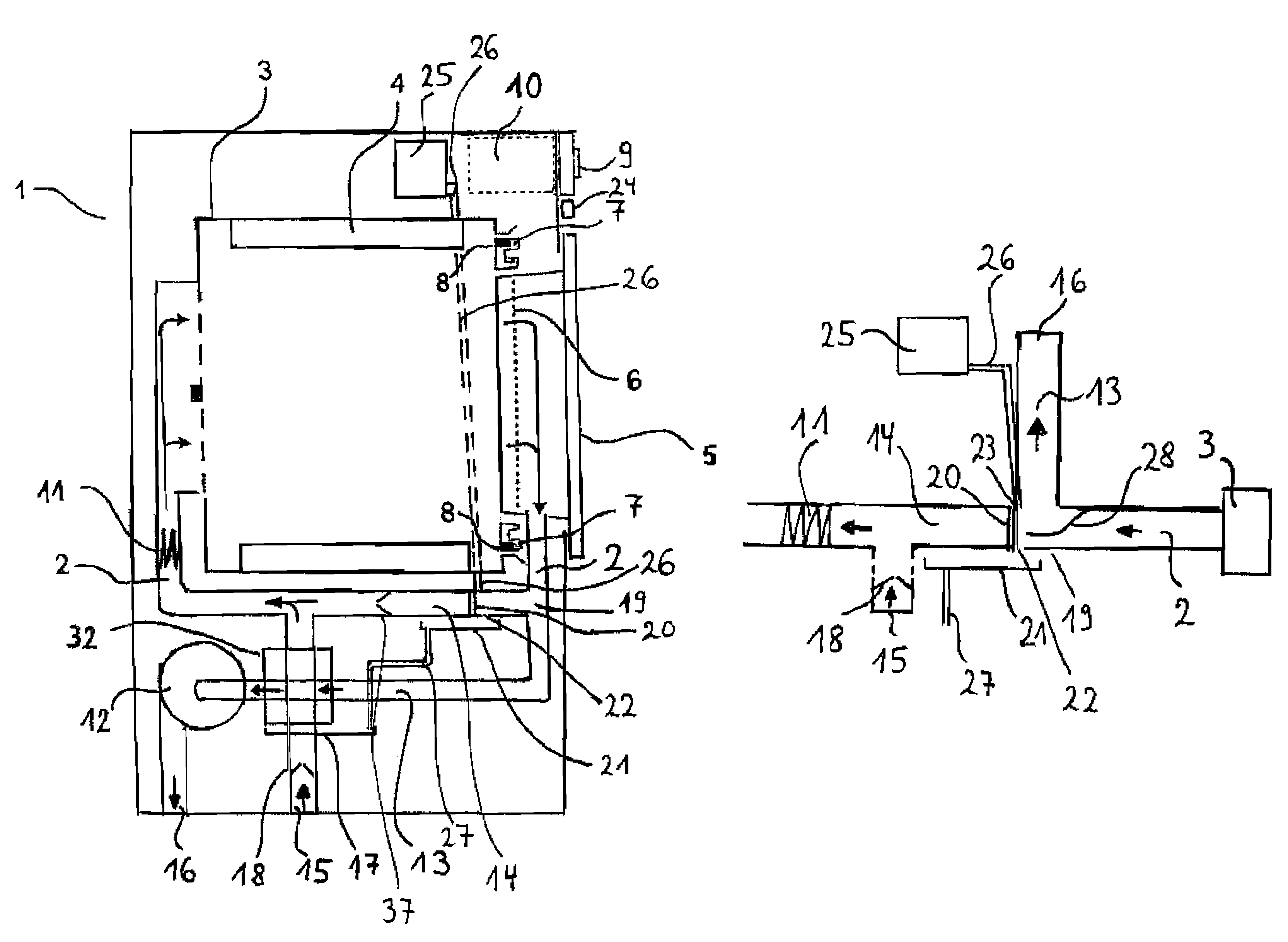
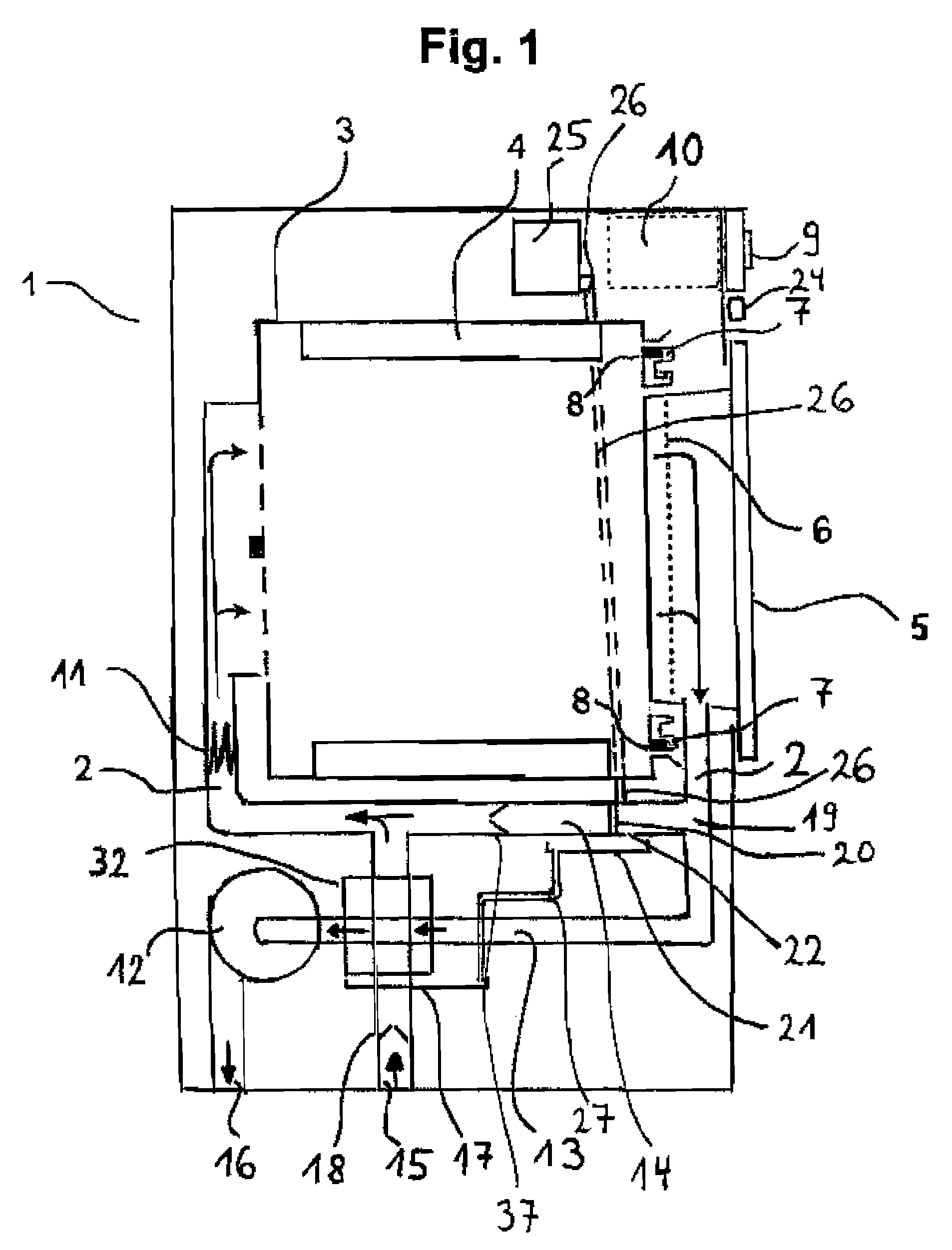
[0051]The dryer 1 shown in FIG. 1 variant has a drum that is rotatable about a horizontal axis as a drying chamber 3, fixed inside of which are baffles 4 for moving laundry during a rotation of the drum. Process air is conveyed by means of a blower 12 by way of an electric heater 11, through a drum 3, in a process air duct 2. Ambient air is fed to the process air duct 2 by way of a supply air duct 15 or drawn in by means of the blower 12. After passing through the drum 3 the moist, warm process air is split at a branching-off point 19 into a recirculated air stream in a recirculated air duct 14 and an exhaust air stream in an exhaust air duct 13. Disposed in the exhaust air duct 13 is an air-to-air-heat exchanger 32 in which the process air (in this case: exhaust air) is cooled and, following condensation of the moisture contained therein, is ducted to the exhaust air outlet 16.

[0052]A lint filter 20 is disposed in the recirculated air duct at a distance from the branching-off poin...

second embodiment

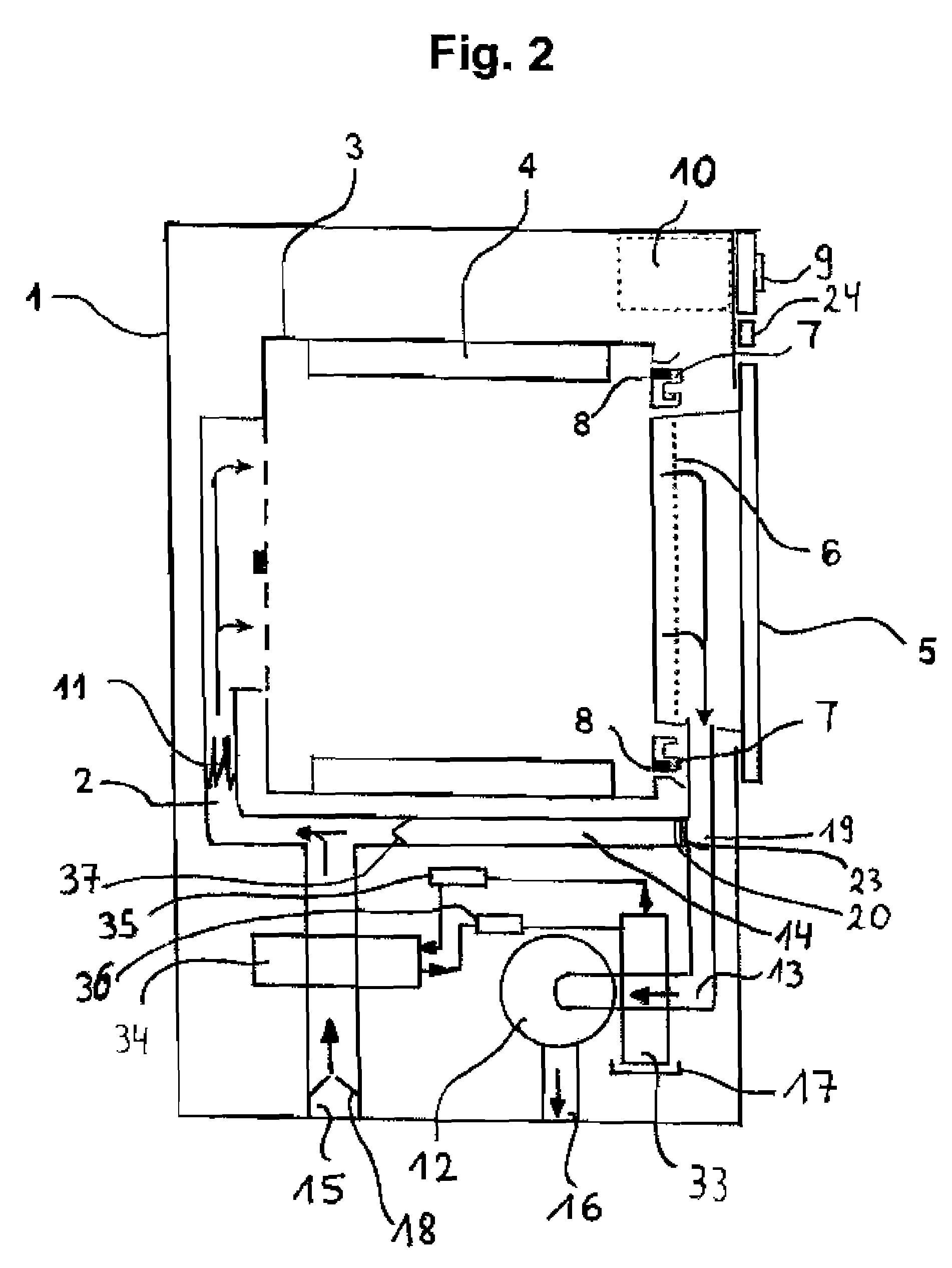
[0056]FIG. 2 shows a vertical section through a dryer variant in which the lint filter 20 is disposed in the recirculated air duct 14 at the branching-off point 19 of the recirculated air duct 14 from the process air duct 2 and heat recovery takes place by means of a heat pump. In this case the warm, moisture-laden process air is channeled into the evaporator 33 of a heat pump circuit 33,34,35,36. The evaporator 33 therefore forms the heat sink 33. The cooled process air is conveyed in the exhaust air duct 13 via the exhaust air outlet 16 to the ambient air.

[0057]The cooling agent of the heat pump evaporated in the evaporator 33 is directed via a compressor 37 to the condenser 34. In the condenser 34, which represents the heat source 34, the cooling agent condenses, releasing heat to the process air flowing in the supply air duct 15 in the process. The cooling agent, which is now present in liquid form, is channeled back to the evaporator 33 again via a restrictor 36, thereby closi...


PUM


Abstract

A dryer includes a drying chamber for the articles to be dried, a supply air duct, a process air duct, a heater in the process air duct for heating process air, a blower that guides the heated process air over the articles to be dried, an exhaust air duct that directs exhaust air to an exhaust air outlet, and an internally and / or externally cleanable lint filter in a recirculated air duct that splits at a branching-off point from the process air duct to the heater and the exhaust air duct which leads to the exhaust air outlet, and wherein the recirculated air duct joins the supply air duct upstream of the heater.

Description

BACKGROUND OF THE INVENTION[0001]The invention relates to a dryer with recirculated air proportion as well as to a preferred method for its operation.[0002]With regard to the prior art, reference is made to the publication WO 2008 / 110449 A1, whose disclosure is to be incorporated by reference in its entirety in the present disclosure.[0003]A clothes tumble dryer is generally operated as a vented or condenser dryer. Condenser dryers, whose principle of operation is based on the condensation of the moisture evaporated from the laundry by means of warm process air, require no vent hose and enable energy to be recovered from the heated process air, through use of a heat pump for example. The condensate accumulating in the condenser dryer is collected and either pumped away or disposed of by manual emptying of a collecting vessel. In the case of a vented dryer, on the other hand, the air laden with moisture after passing through a laundry drum is generally ducted out of the dryer. Genera...

Claims


Application Information

Patent Timeline
Patent Type & Authority Patents(United States)
IPC IPC(8): F26B3/00
CPCD06F58/22
Inventor STEFFENS, GUNTER
Owner BOSCH SIEMENS HAUSGERATE GMBH
Why Eureka
Try Eureka