Grooving supply device for flux cored wire solder

a supply device and flux core technology, applied in the direction of welding/cutting media/materials, manufacturing tools, solventing apparatus, etc., can solve the problems of defective products produced, difficult to stably transfer the wire solder only by a necessary length, and it is almost impossible to retract the wire solder once grooved, etc., to achieve reliable and stably transfer, simple and rational design structure

Active Publication Date: 2012-08-14
JAPAN UNIX
View PDF3 Cites 0 Cited by
  • Summary
  • Abstract
  • Description
  • Claims
  • Application Information

AI Technical Summary

Benefits of technology

[0007]Thus, an object of the present invention is to provide a grooving supply device for flux cored wire solder, which can reliably apply a grooving process to the wire solder and can reliably and stably advance and retract the grooved wire solder only by a necessary amount.
[0016]In the present invention, wire solder is transferred by a feed blade including intermittent engaging claws, and the wire solder is grooved by a grooving blade including a continuous blade edge. Therefore, the wire solder can be reliably and stably transferred only by a necessary amount, and, at the same time, a grooving process can be reliably applied to the wire solder. Especially, the wire solder that once grooved can be reliably retracted by the feed blade only by a necessary amount.
[0017]A second roller is provided with both the feed blade and the grooving blade, and the second roller has both a function of feeding the wire solder and a function of grooving the wire solder, and consequently, the grooving supply device can have a very simple and rational design structure

Problems solved by technology

The evaporated flux and the melted solder are splashed around to adhere to a printed board and electronic components, and there arises a problem that defective products are produced.
However, in the above prior art, since a slip easily occurs between the wire solder and the guide roller or the grooving blade, it is very difficult to stably transfer the wire solder only by a necessary length while a grooving process is applied to the wire solder.
However, in the above prior arts, it is almost impossible to retract wire solder that once grooved.
Thus, the prior art cannot be applied as they are to the automatic soldering machine.

Method used


Image

  • Grooving supply device for flux cored wire solder
  • Grooving supply device for flux cored wire solder
  • Grooving supply device for flux cored wire solder

Examples


Embodiment Construction

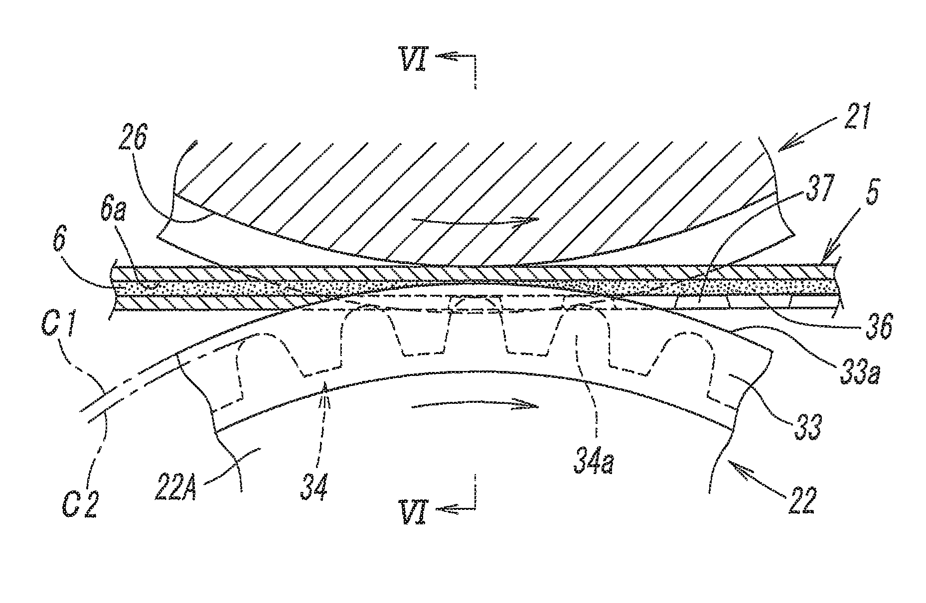
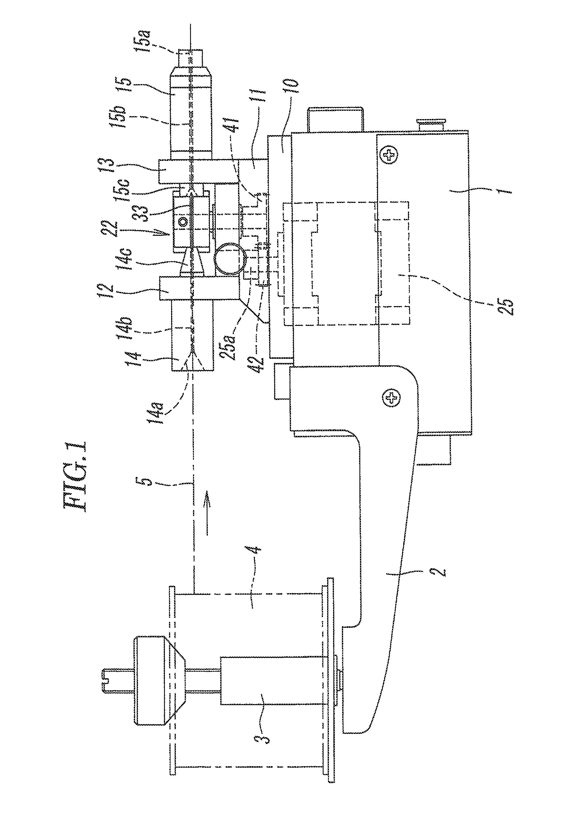
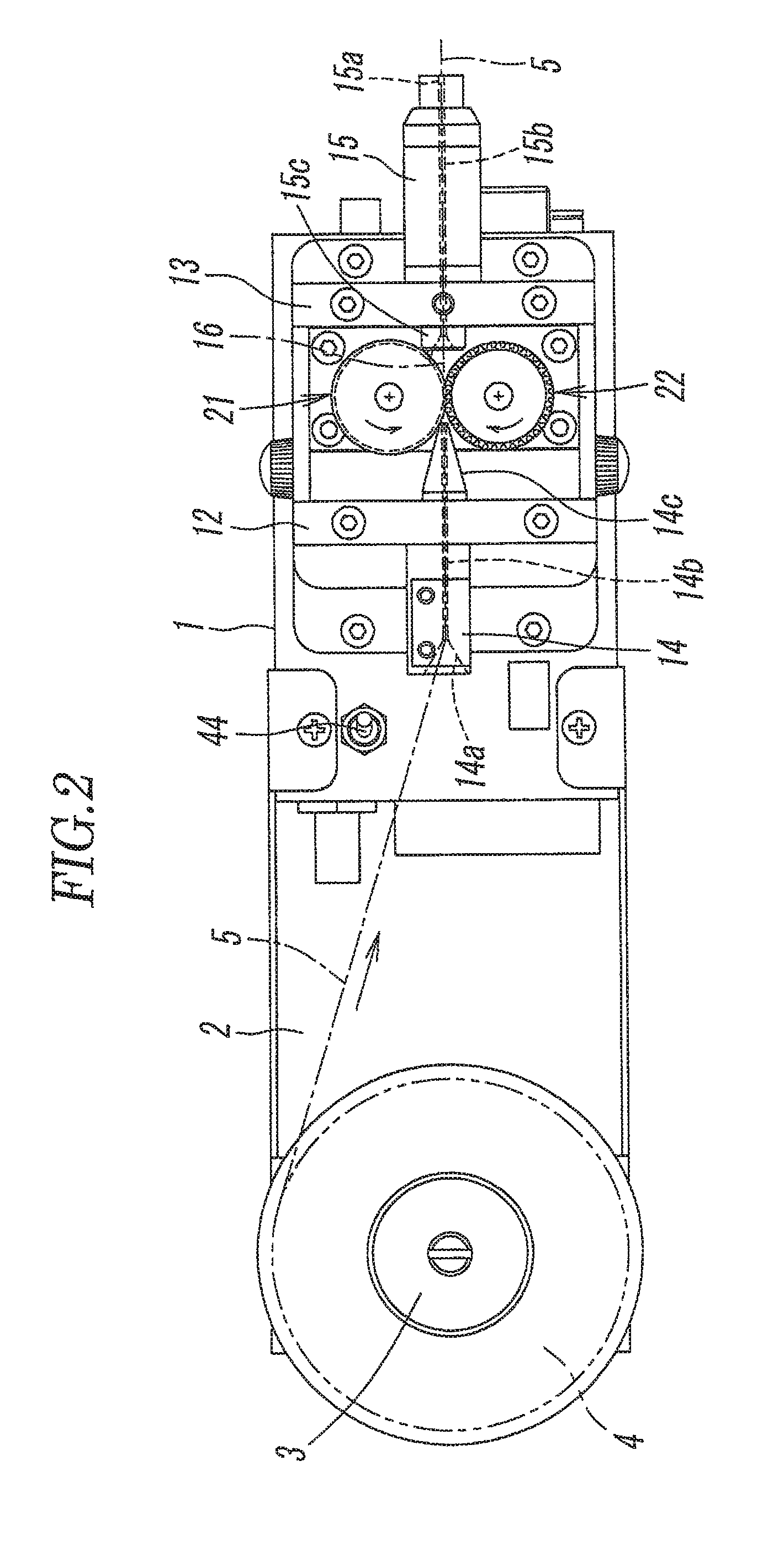
[0031]FIGS. 1 and 2 show a grooving supply device for flux cored wire solder according to the present invention. The grooving supply device has a case 1 having a rectangular box shape. An arm 2 extends from one end of the case 1, and a reel fitting shaft 3 is rotatably attached to the tip end of the arm 2. A solder reel 4 is mounted on the reel fitting shaft 3, and wire solder 5 filled with flux 6 (see, FIGS. 5 and 6) at its core is wound around the solder reel 4.

[0032]A lid plate 10 and a bedplate 11 are overlapped and fixed onto one surface of the case 1 (the top surface in FIG. 1). Two nozzle mounting members 12 and 13 are mounted on the bedplate 11 at a distance from each other. The nozzle mounting member 12 has at one side an inlet nozzle 14, and the nozzle mounting member 13 has at one side an outlet nozzle 15. The inlet nozzle 14 introduces the wire solder 5 drawn out from the solder reel 4 from a solder feed port 14a. The outlet nozzle 15 guides the wire solder 5, fed from t...


PUM

PropertyMeasurementUnit
angleaaaaaaaaaa
angleaaaaaaaaaa
diameteraaaaaaaaaa

Abstract

A first roller is arranged on one side of a transfer path for transferring flux cored wire solder, and a second roller is arranged on the other side. The first roller has on its outer circumference a guide groove in which the wire solder is fitted. The second roller is provided, with a grooving blade and a feed blade closely contacted to each other. The grooving blade comprises a continuous blade edge on the outer circumference, and the feed blade has on its outer circumference a plurality of engaging claws intermittently formed at a constant pitch. The second roller is driven and rotated to thereby advance and retract the wire solder by means of the feed blade, and thus the wire solder is grooved by the grooving blade.

Description

CROSS REFERENCE TO RELATED APPLICATIONS[0001]This application claims priority to Japanese Patent Application No. 2010-033627, filed on Feb. 18, 2010, which is incorporated by reference herein in its entirety.TECHNICAL FIELD[0002]The present invention relates to a grooving supply device for flux cored wire solder which applies a grooving process to a flux cored wire solder and is used for transferring the grooved wire solder toward an object to be soldered.BACKGROUND OF THE ARTDescription of the Related Art[0003]Wire solder for soldering electronic components contains flux for the purpose of increasing the surface tension of the molten solder, preventing generation of oxides, and increasing the wettability and diffusivity of solder. The melting point of flux is lower than the melting point of solder, and therefore, when wire solder is heated by the heat of a soldering tip in soldering, the flux is evaporated, whereby the wire solder rapidly expands to cause a phenomenon like an explo...

Claims


Application Information

Patent Timeline
Patent Type & Authority Patents(United States)
IPC IPC(8): B23K35/40
CPCB23K3/063B23K35/40
Inventor MIYAMA, CHIAKI
Owner JAPAN UNIX
Why Eureka
Try Eureka