
Programmable electronic timer

a timer and electronic technology, applied in the field of programmable electronic timers, can solve the problems of inability to change, limited programmable functionality, and typically electromechanical design of timers, and achieve the effect of avoiding the occurrence of a void in the house, preventing the void from being filled, and avoiding the void

Inactive Publication Date: 2012-08-14
GOOGLE LLC
View PDF9 Cites 6 Cited by
  • Summary
  • Abstract
  • Description
  • Claims
  • Application Information

AI Technical Summary

Benefits of technology

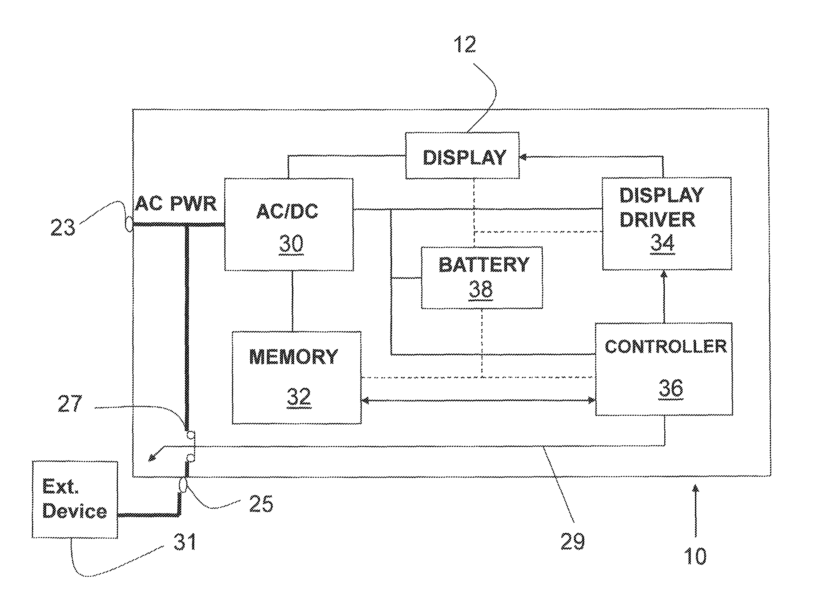
The patent describes a device and method to control a programmable portable electronic timer to provide power to an external electrical device. The device includes a housing with function buttons, a display, and two electrical power connectors. The device also has internal electronic circuitry including an AC / DC converter, a memory, and a controller. The second electrical power connector automatically provides power to the external device during a selected time period based on user-control information stored in the memory. The method allows for selective power provision to the external device with unique start and stop times for each day of operation. The device can also continue to display timer information without being affected by periods of power unavailability. The technical effects of this patent include improved control over power provision to external electrical devices and uninterrupted timer operation even during power unavailability.

Problems solved by technology

As described above, such timers are typically electro-mechanical in design and have limited programmable functionality.
An obvious disadvantage of these types of rotary electro-mechanical timers is that all pre-selected start and stop times are, once set by a user via the insertion of the mechanical start and stop pins in the rotary dial, incapable of being changed (varied) unless the pins are physically pulled out by the user and reinserted into different holes to indicate a different mechanical programming of the timer.
However, many people who take a vacation, go on a business trip, or participate in any other activity which causes their home or business to be unoccupied for a period of days or weeks, typically use such an electro-mechanical rotary timer to attempt to fool any potential burglar, or nosey neighbor, that they are home and are not away, via the automatic turning on and off of a lamp in the home or business.
Thus, they would be susceptible to a “casing” of their house by a potential burglar who will surely notice that a light is being turned on and off at the same time each day, and that no other signs of human activity appear at the house.
Another disadvantage of these types of rotary electro-mechanical timers is that pre-selected start and stop times are not capable of being precisely chosen.
An additional disadvantage is that such an electro-mechanical timer device cannot operate when there is a loss of electrical power being supplied to the device, which may occur during an electrical thunderstorm, nearby utility work, etc., while the home or business owner is away.
Thus, if power is lost at any time while the owner is away the electro-mechanical timer cannot operate and the light will not turn on and off as desired.
Furthermore, even if power is restored to the timer after several minutes (or worse, several hours or days) the timer will resume operation at the point of time that power is restored, but the times for turn-on and turn-off of the light previously set by the owner are now skewed by the time period of the power outage.

Method used


Image

  • Programmable electronic timer
  • Programmable electronic timer
  • Programmable electronic timer

Examples


Embodiment Construction

[0024]In the following detailed description of exemplary embodiments of the general inventive concept, specific exemplary embodiments in which the general inventive concept may be practiced are described in sufficient detail to enable those skilled in the art to practice any invention claimed herein. It is to be understood that other embodiments may be utilized and that logical, architectural, programmatic, mechanical, electrical and other changes may be made without departing from the spirit or scope of the general inventive concept. The following detailed description of the general inventive concept is not to be taken in a limiting sense, and the scope of any invention claimed herein is defined only by the appended claims.

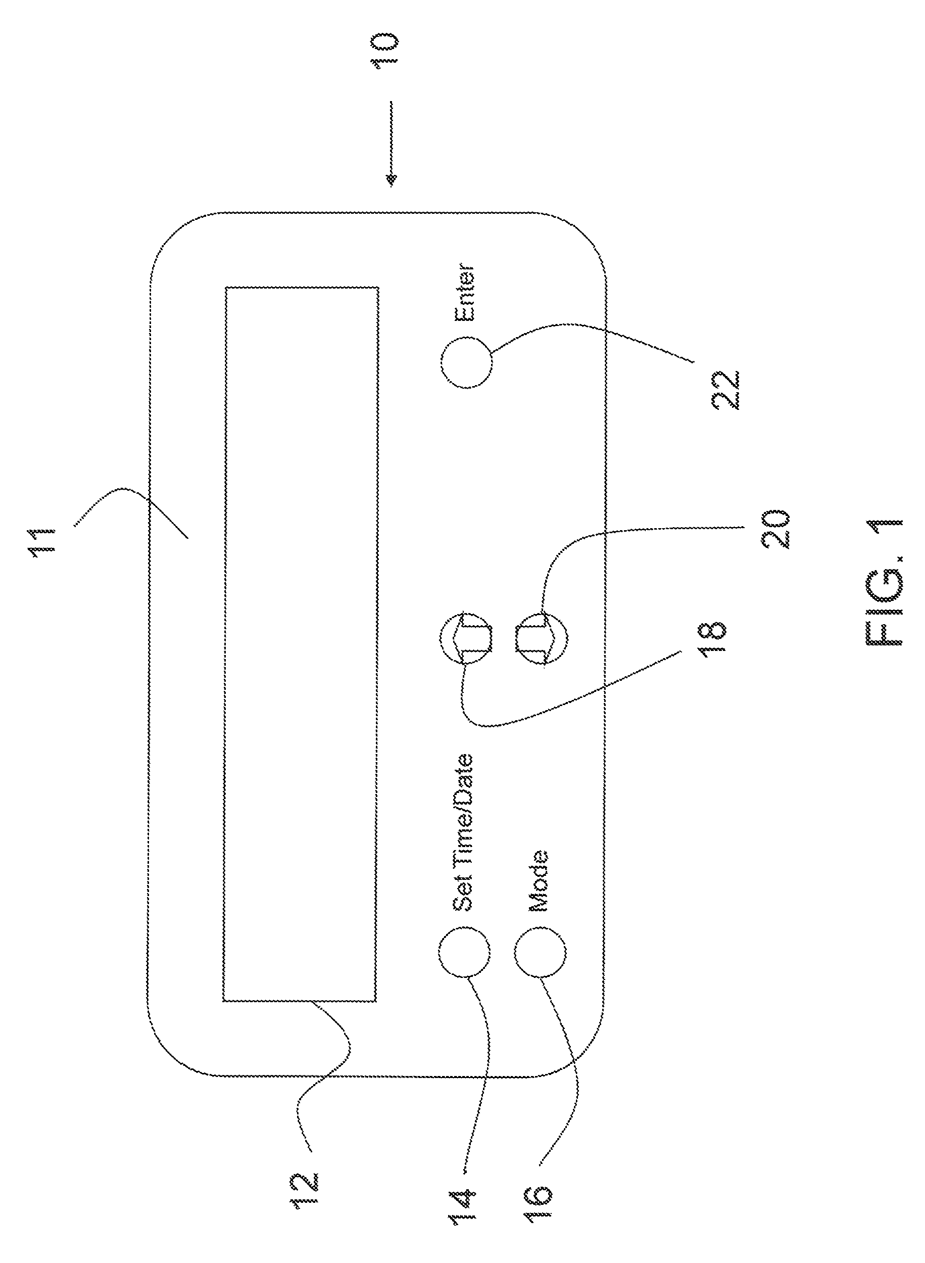
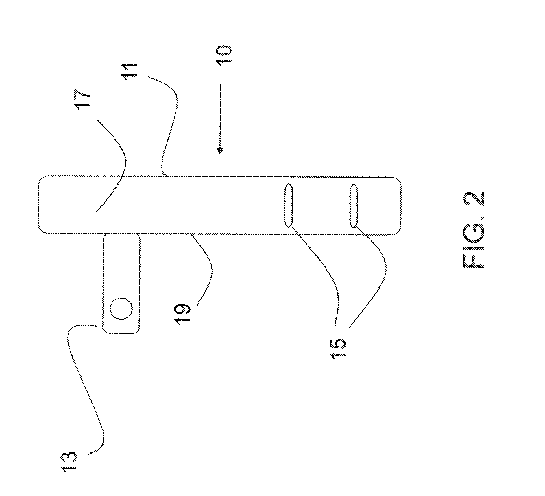
[0025]FIG. 1 depicts an illustration of the front view of the timer device 10, according to an embodiment of the present general inventive concept. The timer device 10 includes a digital visual display 12 and various user functions buttons. In this embodiment, a ...


PUM


Abstract

A device and method to control a programmable portable electronic timer to selectively provide AC power to an external electrical device by selecting a plurality of varying start times and stop times for each of at least two days, where each start time and stop time may be unique, and whereby the start / stop times define a period of timer operation to provide AC power to an external electrical device. An uninterrupted “count down” of timer information stored within the timer while AC power is unavailable to the timer is also provided, such that when AC power is restored to the timer, the providing of AC power to the external electrical device is not skewed by any period of time that the AC power is unavailable to the timer.

Description

BACKGROUND OF THE INVENTION[0001]1. Field of the Invention[0002]The invention relates generally to a device and method for programmably and automatically setting varying start and stop times of operation for a portable electronic timer device for providing, and cutting off, electrical power from a local AC power grid with respect to one or more external electrical devices connected to the electronic timer.[0003]2. Description of the Related Art[0004]As understood in the art, portable electronic timers may be used within homes or businesses to provide power to other electrical devices plugged into such a timer at certain selected times. Typically, such timers are electro-mechanical in design and are plugged into a power outlet within a home or business to turn on and off lights, or other electrical devices which are connected to the timer, for various reasons. For example, for a home or small business, a lighting device, such as a lamp, may be connected to such a timer so that the la...

Claims


Application Information

Patent Timeline
Patent Type & Authority Patents(United States)
IPC IPC(8): H02J9/00
CPCG04C23/26G04G15/006H02J3/00H02J9/062
Inventor KING, JOSEPH W.
Owner GOOGLE LLC
Learn More