Image data analog-to-digital conversion method and image sensor
A technology of image data and analog-to-digital conversion, which is applied in the direction of image communication, TV, color TV parts, etc., can solve the problems of image quality impact, chip noise, and digital module power consumption increase, etc., to achieve power consumption reduction , reduce power consumption and floor noise, and reduce the effect of counting times
- Summary
- Abstract
- Description
- Claims
- Application Information
AI Technical Summary
Problems solved by technology
Method used
Image
Examples
Embodiment 1
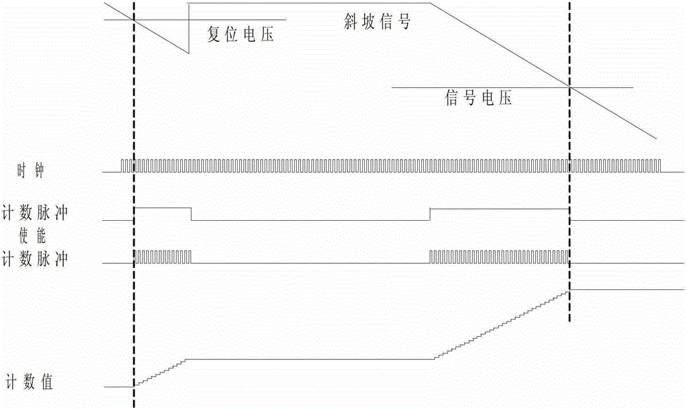
[0052] Such as Figure 5 As shown, it is one of the implementation methods of directly quantifying the difference between the pixel reset voltage and the signal voltage by using the image data analog-to-digital conversion method of the present invention. During the first quantization, a reset voltage is placed at the input of the comparator. The ramp signal starts at t0 and ends at t3. The output of the comparator starts to toggle at t1. The first falling edge of the low-speed clock after the comparator toggles occurs at t2. The first falling edge of the low-speed clock after the end of the ramp signal occurs at t4. The high-bit counter starts counting up from t2 and stops counting at t4. The low counter starts counting up at t1 and ends counting at t2. In the second quantization, the pixel signal voltage is placed at the input of the comparator. The ramp signal starts at t5 and ends at t9. The first falling edge of the low-speed clock after the start of the ramp signal ...
Embodiment 2
[0054] Image 6 Another implementation method is to directly quantify the difference between the pixel reset voltage and the signal voltage by using the image data analog-to-digital conversion method of the present invention. During the first quantization, a reset voltage is placed at the input of the comparator. The ramp signal starts at t0 and ends at t4. The first falling edge of the low-speed clock after the start of the ramp occurs at t1. The output of the comparator starts to toggle at t2. The first falling edge of the low-speed clock after the comparator flips occurs at t3. The high-bit counter starts counting up from t1 and stops counting at t3. The low counter starts counting down at t2 and ends counting at t3. In the second conversion, the pixel signal voltage is placed at the input of the comparator. The ramp signal starts at t5 and ends at t8. The comparator toggles at t6. The first falling edge of the low-speed clock after the comparator flips occurs at t7. ...
Embodiment 3
[0056] Figure 7Another implementation method is to directly quantify the difference between the pixel reset voltage and the signal voltage by using the image data analog-to-digital conversion method of the present invention. During the first quantization, a reset voltage is placed at the input of the comparator. The ramp signal starts at t0 and ends at t4. The first falling edge of the low-speed clock after the start of the ramp occurs at t1. The output of the comparator starts to toggle at t2. The first falling edge of the low-speed clock after the comparator flips occurs at t3. The high-bit counter starts counting down from t1 and stops counting at t3. The low counter starts counting up at t2 and ends counting at t3. In the second conversion, the pixel signal voltage is placed at the input of the comparator. The ramp signal starts at t5 and ends at t9. The first falling edge of the low-speed clock after the start of the ramp signal to convert the pixel signal voltage o...
PUM
 Abstract
Description
Claims
Application Information
 - R&D
- Intellectual Property
- Life Sciences
- Materials
- Tech Scout
- Unparalleled Data Quality
- Higher Quality Content
- 60% Fewer Hallucinations
Browse by: Latest US Patents, China's latest patents, Technical Efficacy Thesaurus, Application Domain, Technology Topic, Popular Technical Reports.
© 2025 PatSnap. All rights reserved.Legal|Privacy policy|Modern Slavery Act Transparency Statement|Sitemap|About US| Contact US: help@patsnap.com


