Sound emission and collection device

a collection device and sound technology, applied in the direction of transducer details, electrical transducers, electrical apparatus, etc., can solve the problems of large amount of wraparound sound from the speaker to the microphone, heavy processing burden on the echo canceller function, etc., and achieve the effect of further improving the s/n ratio

Active Publication Date: 2012-08-14
YAMAHA CORP
View PDF22 Cites 29 Cited by
  • Summary
  • Abstract
  • Description
  • Claims
  • Application Information

AI Technical Summary

Benefits of technology

[0009]In the present invention, the plurality of unidirectional microphones and speakers are respectively installed on the circumferences in which the same axis is set as the center. The directivities of the unidirectional microphone and the speaker are installed in opposite directions. Therefore, a wraparound sound from the speaker to the unidirectional microphone can be suppressed. Since both the speaker and the unidirectional microphone are installed on the circumferences in which the same axis is set as the center, a compact configuration is provided.
[0013]In the above-mentioned configuration, a signal having a highest sound pressure level is selectively output among sound signals collected in the respective unidirectional microphones. Thereby, an S / N ratio can be further improved.
[0014]In the present invention, the signal processing means may further estimate a sound source direction by adding sound signals collected by a plurality of adjacent unidirectional microphones and output a signal achieved by adding the sound signals collected by the plurality of adjacent unidirectional microphones to the rear stage.
[0015]In the above-mentioned configuration, sound signals collected from adjacent unidirectional microphones are added in each unidirectional microphone. Moreover, a signal having the highest sound pressure level is selectively output among the added sound signals. Thereby, an S / N ratio can be further improved.
[0018]Each of the plurality of unidirectional microphones is arranged on the first surface side in a circumferential shape. On this occasion, the center of the sound emission surface and the circle center are on the same perpendicular line with respect to the first surface and the second surface, and a center direction of the circle is installed to be an axis direction of directivity, that is, a direction of high sound collection sensitivity.
[0025]In this configuration, a collected sound signal of a unidirectional microphone in which a directional axis is toward the sound source direction has a higher signal strength than collected sound signals of other unidirectional microphones, that is, uses a higher sound pressure level, and a collected sound signal having the highest signal strength is selectively output among the collected sound signals of the respective unidirectional microphones. Thereby, the signal strength of a collected sound signal from the sound source direction is relatively high and a collected sound signal having a high S / N ratio can be obtained.

Problems solved by technology

However, in the configuration of Patent Document 1, a compact configuration is provided, but the speaker and the microphone are close to each other and the amount of wraparound sound from the speaker to the microphone is large.
For this reason, there is still a problem in that a sound emitted from the speaker is apt to wrap around the microphone and a heavy processing burden is imposed on the echo canceller function.

Method used


Image

  • Sound emission and collection device
  • Sound emission and collection device
  • Sound emission and collection device

Examples


first embodiment

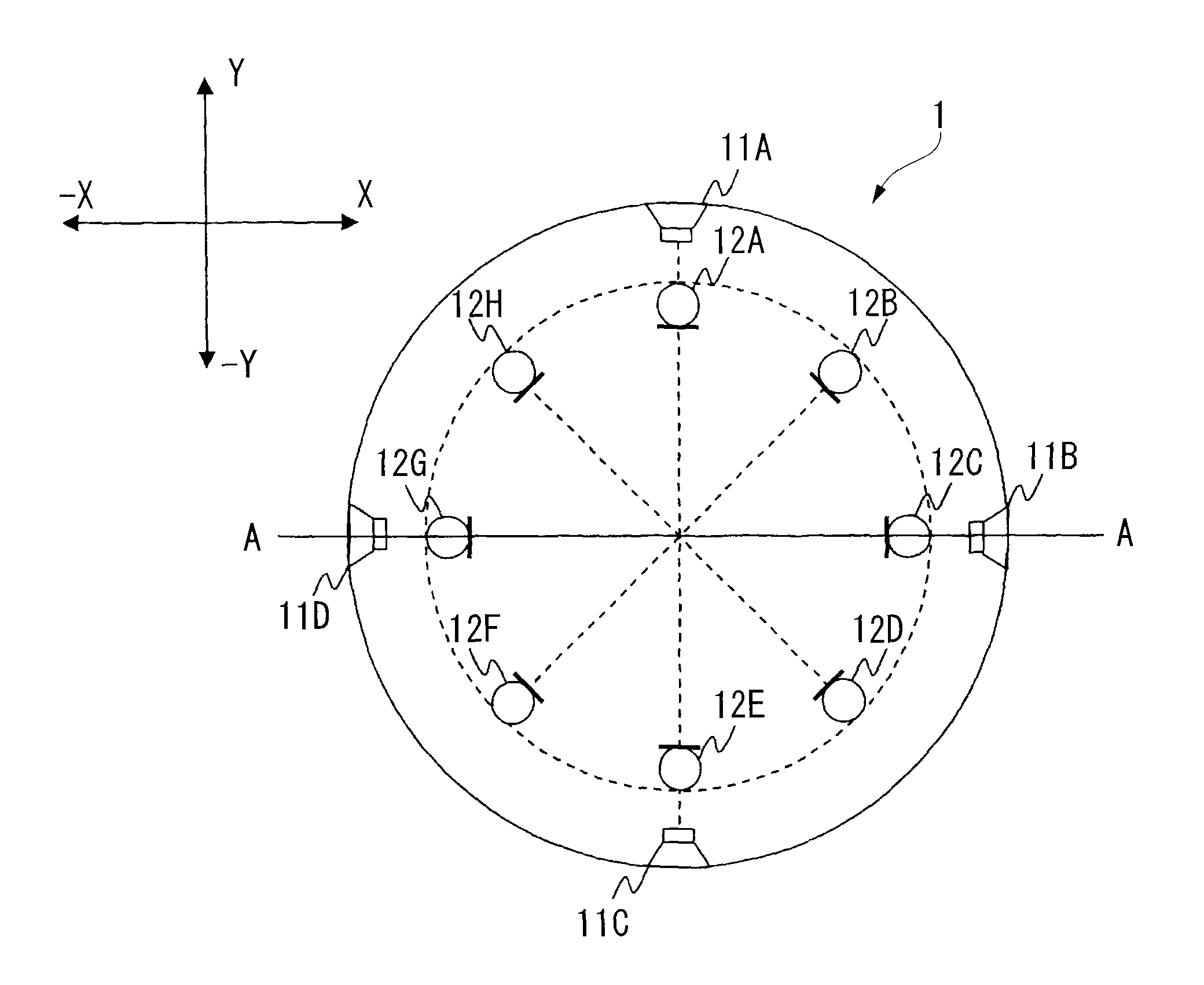
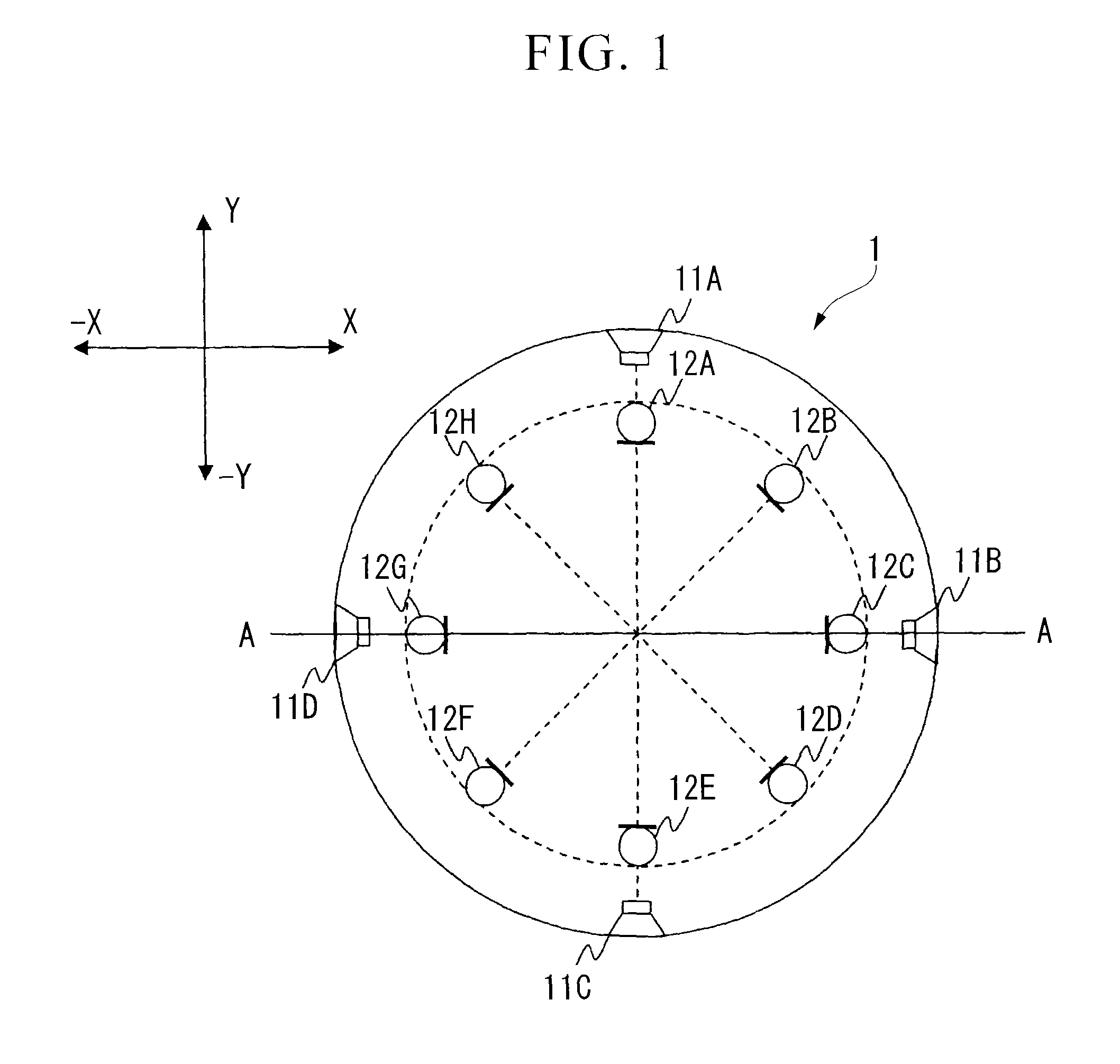
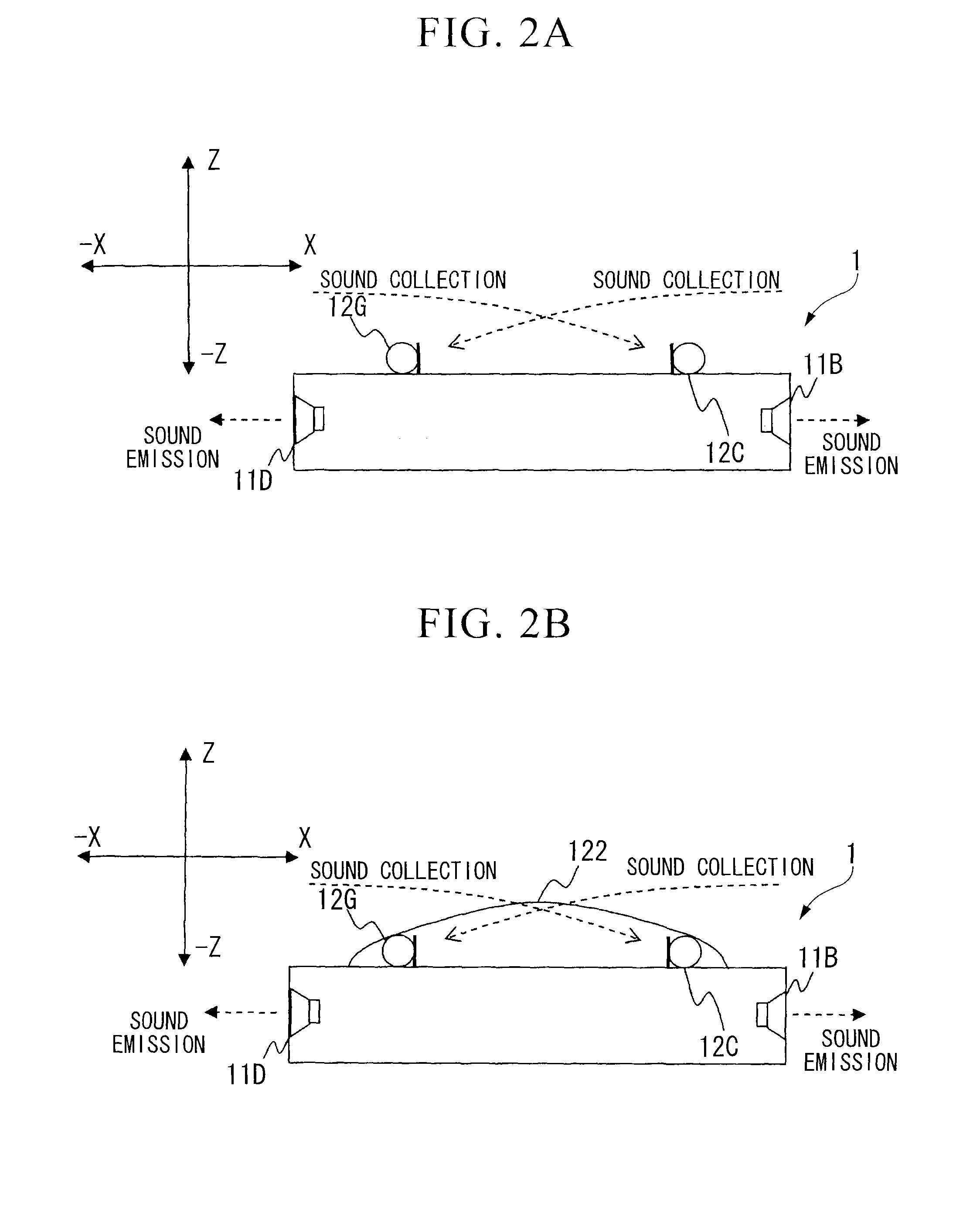
[0107]A sound emission and collection device according to an embodiment of the present invention will be described with reference to the drawings. FIG. 1 is a top view of the sound emission and collection device according to the embodiment, and FIG. 2A is an A-A cross-sectional view in FIG. 1. In FIG. 1, the right side on the paper surface is the X direction, the left side is the −X direction, the upper side is the Y direction, and the lower side is the −Y direction. In FIG. 2A, the right side on the paper surface is the X direction, the left side is the −X direction, the upper side is the Z direction, and the lower side is the −Z direction.

[0108]The sound emission and collection device includes a circular cylindrical shaped case 1, a plurality of (in this example, four) speakers 11A˜11D arranged at equal intervals on a concentric circle on an outermost circumference portion of the case 1, and a plurality of (in this example, eight) microphones 12A 12H (unidirectional microphones) a...

embodiment 1

[0130]FIG. 7 shows a structure of a sound emission and collection device in another example. FIG. 7 is a top view and a cross-sectional view showing the sound emission and collection device of another example. FIG. 7A is the top view of the sound emission and collection device, and FIG. 7B is the A-A cross-sectional view in FIG. 7A of the same. In FIG. 7A, the right side on the paper surface is the X direction, the left side is the −X direction, the upper side is the Y direction, and the lower side is the −Y direction. In FIG. 7B, the right side on the paper surface is the X direction, the left side is the −X direction, the upper side is the Z direction, and the lower side is the −Z direction. Components common with those of the sound emission and collection device shown in FIG. 1 and FIG. 2 are assigned the same reference numerals and signs, and a description thereof is omitted.

[0131]In this example, the sound emission and collection device includes a circular cylindrical shaped ca...

embodiment 2

[0135]Moreover, a sound emission and collection device can have a structure as shown in FIG. 8. FIG. 8 is a top view and a cross-sectional view showing the sound emission and collection device of another example. FIG. 8A is the top view of the sound emission and collection device, and FIG. 8B is the A-A cross-sectional view in FIG. 8A of the same. In FIG. 8A, the right side on the paper surface is the X direction, the left side is the −X direction, the upper side is the Y direction, and the lower side is the −Y direction. In FIG. 8B, the right side on the paper surface is the X direction, the left side is the −X direction, the upper side is the Z direction, and the lower side is the −Z direction. Also in this example, components common with those of the sound emission and collection device shown in FIG. 1 and FIG. 2 are assigned the same reference numerals and signs, and a description thereof is omitted.

[0136]In an example of the same figure, the sound emission and collection device...


PUM


Abstract

It is possible to provide a sound emission and collection device having a compact configuration and being capable of suppressing a wraparound sound from a speaker to a microphone and improving the S / N ratio. In the sound emission and collection device, a plurality of speakers (11) have a sound emission surface arranged on the side surface of a case (1) so that a sound can be emitted in all circumferential directions of the sound emission and collection device. Each of the microphones (12) is arranged with the sound collection direction set in the center direction of the case (1). The microphone (12) and the speaker (11) have directivities opposing to each other. Accordingly, it is possible to minimize a wraparound sound from the speaker (11) to the microphone (12). Moreover, since the speaker (11) and the microphone (12) are arranged on circumferences of concentric circles, it is possible to obtain a compact configuration.

Description

TECHNICAL FIELD[0001]This application is a U.S. National Phase Application of PCT International Application PCT / JP2006 / 325063 and claims priority from Japanese Patent Application No. 2005-364617, filed Dec. 19, 2005, and Japanese Patent Application No. 2005-368052, filed Dec. 21, 2005, the contents of which are all incorporated herein by reference, and relates to a sound emission and collection device integrally including speakers and microphones, and more particularly to a sound emission and collection device having a compact configuration and capable of suppressing a wraparound sound from a speaker to a microphone.BACKGROUND ART[0002]As an audio communication system for performing an audio conference (conference call) in a remote location, an audio conference device integrally including a speaker and a microphone has been released. The audio conference device transmits a sound signal collected by the microphone to a connection destination and emits a sound signal, received from th...

Claims


Application Information

Patent Timeline
Patent Type & Authority Patents(United States)
IPC IPC(8): H04R3/00
CPCH04R1/403H04R3/005H04R1/406
Inventor ISHIBASHI, TOSHIAKISAITO, KOSUKE
Owner YAMAHA CORP
Why Eureka
Try Eureka