Edge-based resource spin-up for cloud computing

a cloud computing and resource technology, applied in the direction of program control, sustainable buildings, instruments, etc., can solve the problems of increasing complexity, increasing complexity, and requiring additional resources and computing power, so as to improve application performance and improve service quality. the effect of quality and efficiency

Active Publication Date: 2012-08-14
LIMELIGHT NETWORKS
View PDF11 Cites 108 Cited by
  • Summary
  • Abstract
  • Description
  • Claims
  • Application Information

AI Technical Summary

Benefits of technology

[0008]Further aspects of the present invention include dynamically routing requests for applications to one of multiple cloud computing environments. Alternatively, the method may dynamically route an application request to an application that is hosted in multiple clouds (deployed within a management application) based upon a specified criteria. In one embodiment, the routing of requests for the application to a specific cloud in which the application is deployed may be based upon a criteria(s) that the application owner specifies. This may provide the application owner an ability to positively affect quality of service (QoS) for application delivery, ensure uninterrupted access to the application in the event of failure by one or more clouds, and provide more efficient application performance.

Problems solved by technology

Unfortunately, such an implementation does not necessarily provide the best performance or experience for end users who may, for example, be located far away from the centralized cluster.
This problem is further compounded by the fact that applications provided within the “cloud” are becoming more robust and require additional resources and computing power as well as faster response times. Accordingly, the computations being preformed over the web are becoming increasingly more intensive.
As such, with the centralized cluster approach, many of these computations are being routed away from the user which adds to or even causes delays and an unacceptable user experience.
Unfortunately, if the cloud provider is experiencing difficulties (either regionally or globally), the customer has no way to re-route requests to another cloud, and thus performance is dramatically impacted.

Method used


Image

  • Edge-based resource spin-up for cloud computing
  • Edge-based resource spin-up for cloud computing
  • Edge-based resource spin-up for cloud computing

Examples


Embodiment Construction

[0018]The ensuing description provides preferred exemplary embodiment(s) only, and such preferred exemplary embodiments are not intended to limit the scope or applicability of the present invention. Rather, the ensuing description will enable those who are skilled in the art to implement such preferred exemplary embodiment(s). Persons of skill in the art will recognize that various changes may be made in the function and arrangement of elements without departing from the spirit and scope of the invention as set forth in the appended claims.

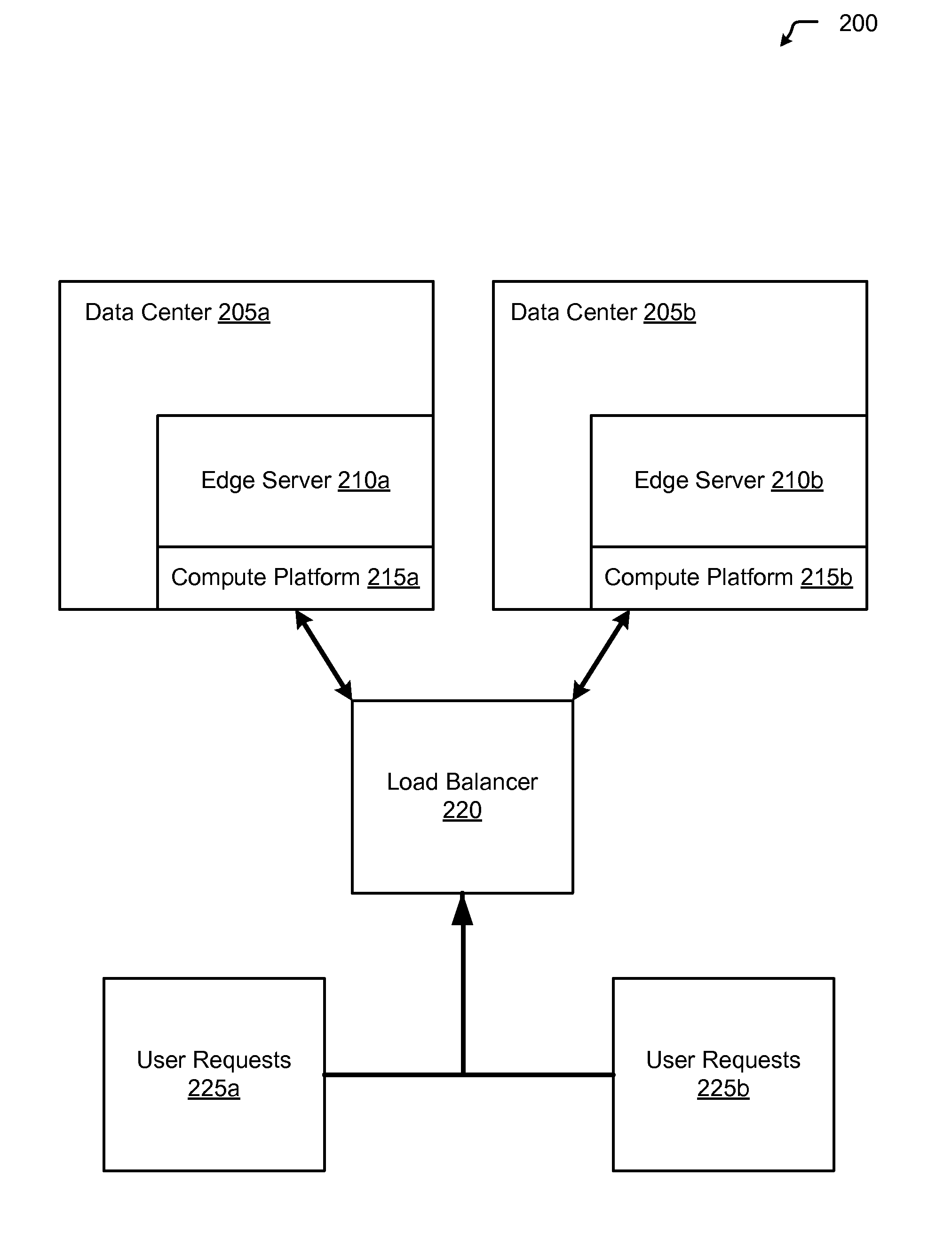
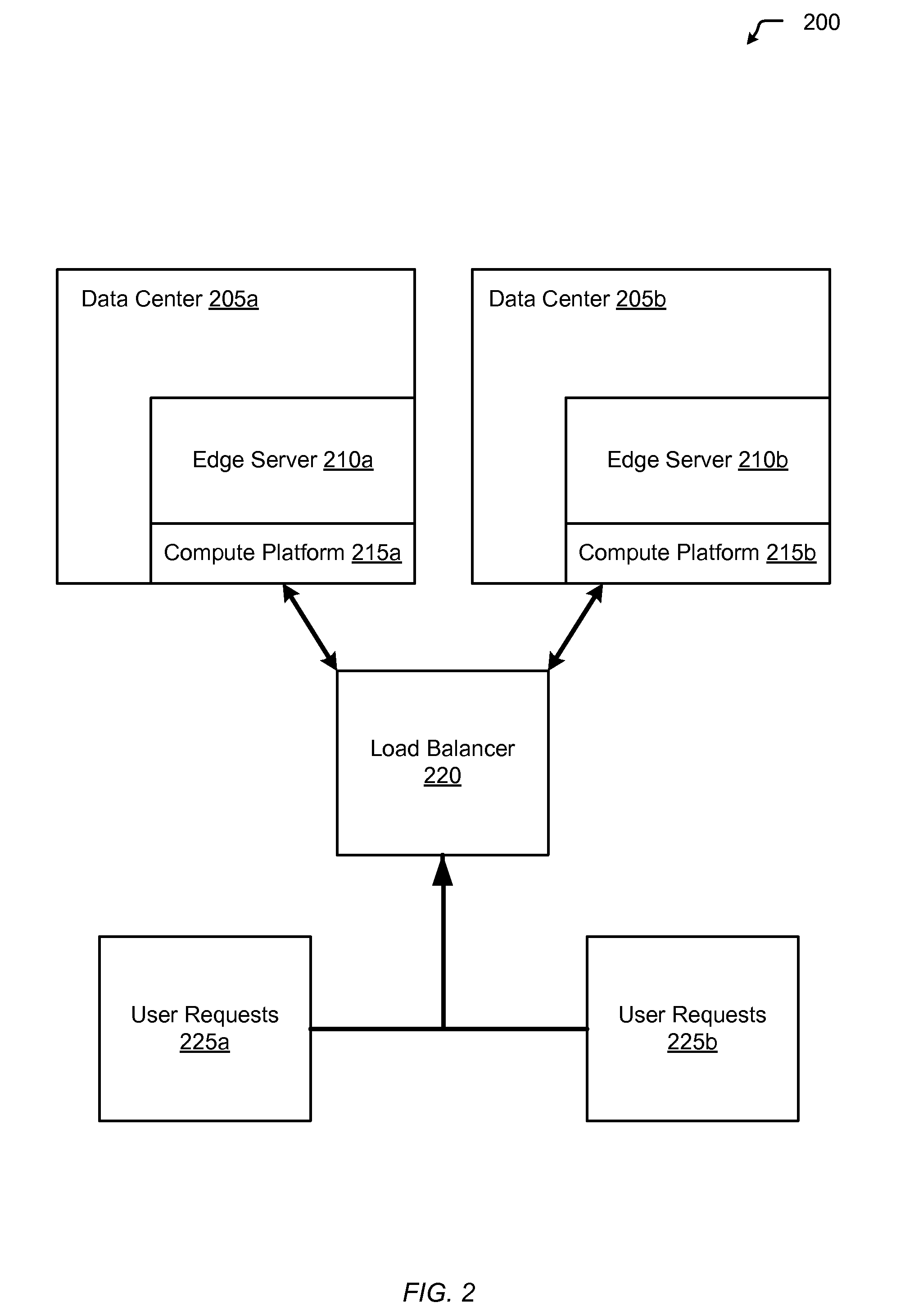
[0019]FIG. 2 shows a system for implementing edge-based resource spin-up for cloud computing, in accordance with one embodiment of the present invention. In one embodiment, edge-based resource spin-up includes carrying out computational activities within a cloud computing environment closer to the end user. As such, an increase in responsiveness as well as a more efficient use of resources is realized. System 200 includes a data center 205a and 20...


PUM


Abstract

Aspects of the present invention include distributing new resources closer to end-users which are making increased demands by spinning-up additional virtualized instances (as part of a cloud provisioning) within servers that are physically near to the network equipment (i.e., web servers, switches, routers, load balancers) that are receiving the requests.

Description

RELATED APPLICATION[0001]This application is related to U.S. patent application Ser. No. 13 / 245,582, filed Sep. 26, 2011, entitled “DYNAMIC ROUTE REQUESTS FOR MULTIPLE CLOUDS”, which is incorporated by reference in its entirety for any and all purposes.BACKGROUND[0002]Presently, compute resources (i.e., applications, etc.) within a cloud provider's network are spun-up in a cluster (e.g., servers which are aggregated in a centralized location, a datacenter, etc.). All requests are load-balanced back to that cluster. Unfortunately, such an implementation does not necessarily provide the best performance or experience for end users who may, for example, be located far away from the centralized cluster.[0003]This problem is further compounded by the fact that applications provided within the “cloud” are becoming more robust and require additional resources and computing power as well as faster response times. Accordingly, the computations being preformed over the web are becoming increa...

Claims


Application Information

Patent Timeline
Patent Type & Authority Patents(United States)
IPC IPC(8): G06F15/173
CPCG06F9/5055G06F9/5072H04L41/0806Y02B60/142Y02B60/167Y02D10/00
Inventor THIREAULT, JASON
Owner LIMELIGHT NETWORKS
Why Eureka
Try Eureka