Door assembly for laminar flow control system

a technology of laminar flow control and door assembly, which is applied in the direction of air intakes, air-flow influencers, transportation and packaging, etc., can solve the problems of increasing the weight, complexity and cost of the aircraft, and the requirement of a relatively large suction force, so as to increase the torsional rigidity of the second door, minimize twisting, and increase the torsional rigidity

Active Publication Date: 2012-08-21
THE BOEING CO
View PDF24 Cites 46 Cited by
  • Summary
  • Abstract
  • Description
  • Claims
  • Application Information

AI Technical Summary

Benefits of technology

[0018]The door assembly may be fluidly connected to the laminar flow control system of the aircraft by a diffuser or other ducting such that when the first door is moved to the open position, the pores of the laminar flow control system may be purged by high pressure external flow captured by the first door and which may be ducted to the suction cavity for discharge through the pores. The discharge of flow through the pores may effectively remove contaminants such as liquid and / or debris that may be trapped in the pores. The discharge of flow through the holes may also prevent contaminants such as water from rain or clouds or de-icing or anti-icing fluid from passing through the pores and entering the suction cavity. In all cases, such contaminants may reduce the effectiveness of the laminar flow control system during various stages of flight.
[0019]When the first door is moved to the closed position and the second door is moved to the open position, a suction force may be generated in the suction cavity. In this regard, the opening of the second door may generate an external region aft of the second door that has an external pressure that is less than a cavity pressure within the suction cavity. The external pressure may result in the generation of the suction force within the suction cavity which may draw the external flow located proximate the porous skin through the pores and into the suction cavity. More specifically, the application of the suction force to the porous skin draws a portion of the boundary layer through the pores. As is know in the art, the drawing in or suctioning of the boundary layer may delay transition of the boundary layer to turbulent flow and may decrease skin friction drag.
[0021]Each one of the doors may be configured to resist torsional deformation. For example, the first door may include a torque box and a pair of first door side walls that may sealingly engage an arrangement of seals in order to increase the torsional rigidity and minimize twist and the potential for flutter of the first door in response to aerodynamic loading on the first door when in the open position. Likewise, the second door may include a pair of second door side walls that may sealingly engage an arrangement of seals in order to increase the torsional rigidity of the second door.
[0022]The technical benefits of the disclosed embodiments include a reduction in the complexity and weight associated with laminar flow control system by combining the first and second doors into a single door assembly. In this regard, the door assembly provides a simple and compact arrangement for use with the passive purging and passive suctioning of a laminar flow control system.

Problems solved by technology

One of the challenges preventing widespread implementation of laminar flow control systems of the suctioning type is the requirement of a relatively large suction force.
While generally effective for their intended purposes, active suctioning systems typically require a variety of flow ducts, control valves and other components that add to the weight, complexity and cost of the aircraft and detract from the aircraft operating efficiency.
Another challenge preventing widespread implementation of laminar flow control systems having porous skins is contamination or blockage of pores which can occur under certain conditions.
Such contamination may include atmospheric contamination and / or manmade contamination which may reduce the effectiveness of laminar flow control systems.
The frozen moisture blocks the pores and reduces the effectiveness of the suctioning system in maintaining laminar flow over the aircraft during cruise.
Manmade contamination such as de-icing fluids applied during ground operations may also reduce the effectiveness of the laminar flow control system by clogging the pores with de-icing fluid.
The accumulation of frost on an aircraft may also reduce the effectiveness of a suctioning system by blocking the pores.
Although frost accumulations on exterior surfaces of the porous skin may eventually sublimate away, moisture or liquid on the interior surfaces of the porous skin may become trapped in the pores and will remain due to the relatively small amount of surface area over which the sublimation would otherwise occur.
Furthermore, local flow velocities inside the pores are relatively low and therefore insufficient to overcome surface tension resistance of the moisture trapped within the pores.
Although effective for their intended purposes, prior art purging systems suffer from several defects that detract from their overall utility.
As may be appreciated, the system architecture of an active purging system such as one which draws pressurized air from an aircraft engine may be functionally and structurally complex.
In addition, the installation of components and machinery for providing the pressurized air adds to the complexity and cost of the aircraft.
Furthermore, additional components of an active purging system may increase the weight of the aircraft which may detract from gains in fuel efficiency otherwise attainable with the laminar flow control system.
As such, conventional engine bleed air may be unavailable on future aircraft for providing pressurized air for use with active purging or suctioning.

Method used


Image

  • Door assembly for laminar flow control system
  • Door assembly for laminar flow control system
  • Door assembly for laminar flow control system

Examples


Embodiment Construction

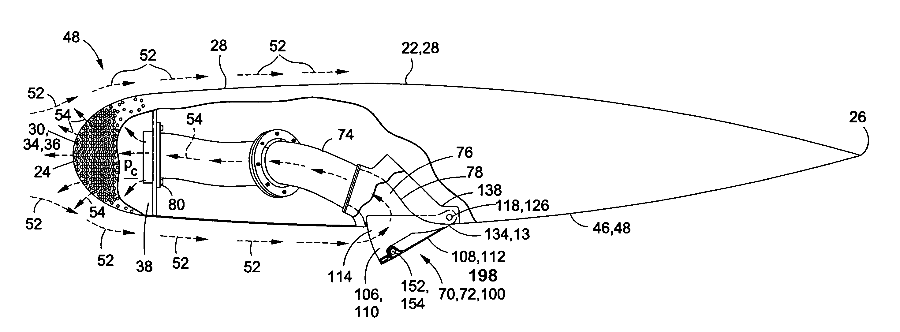
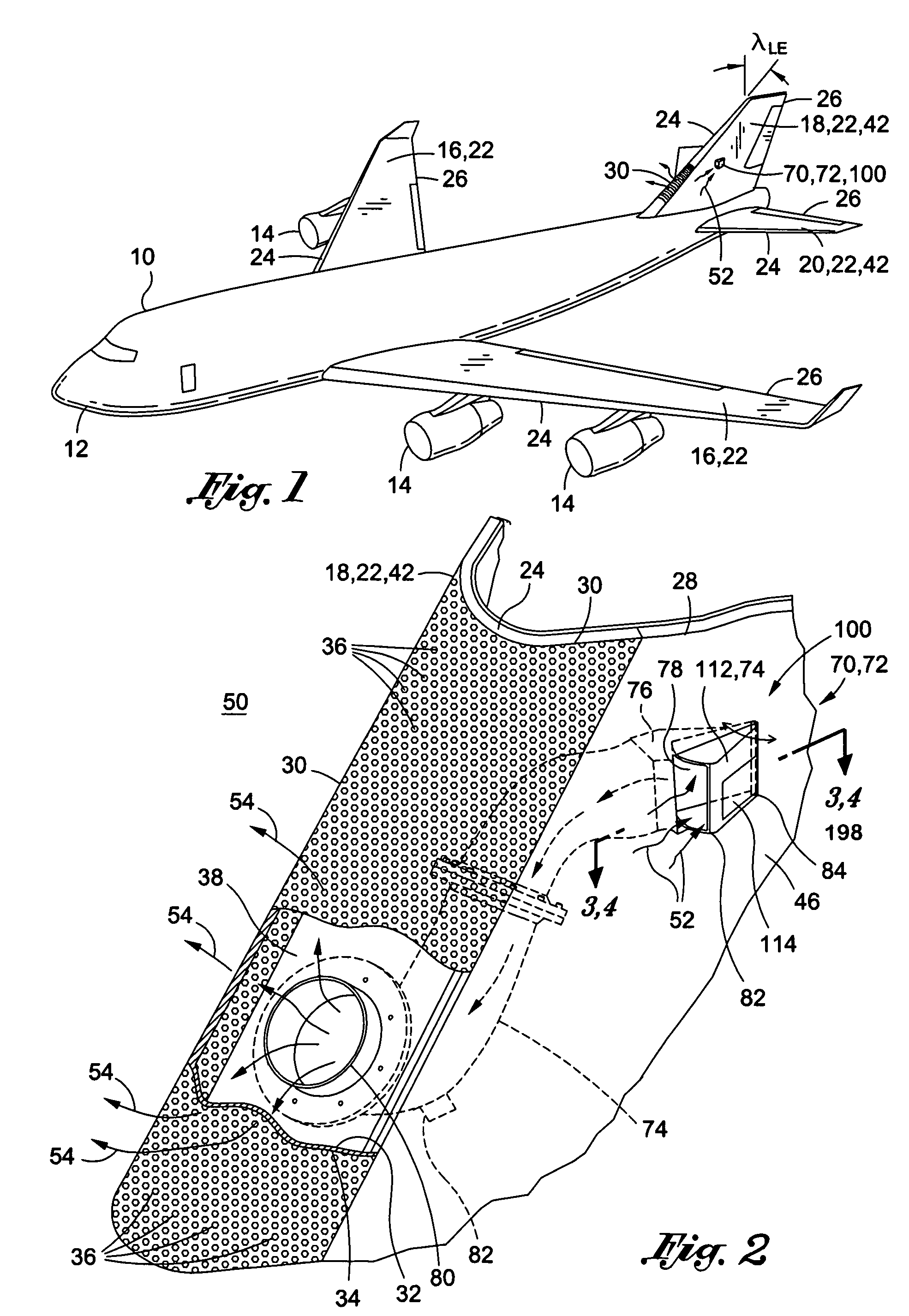
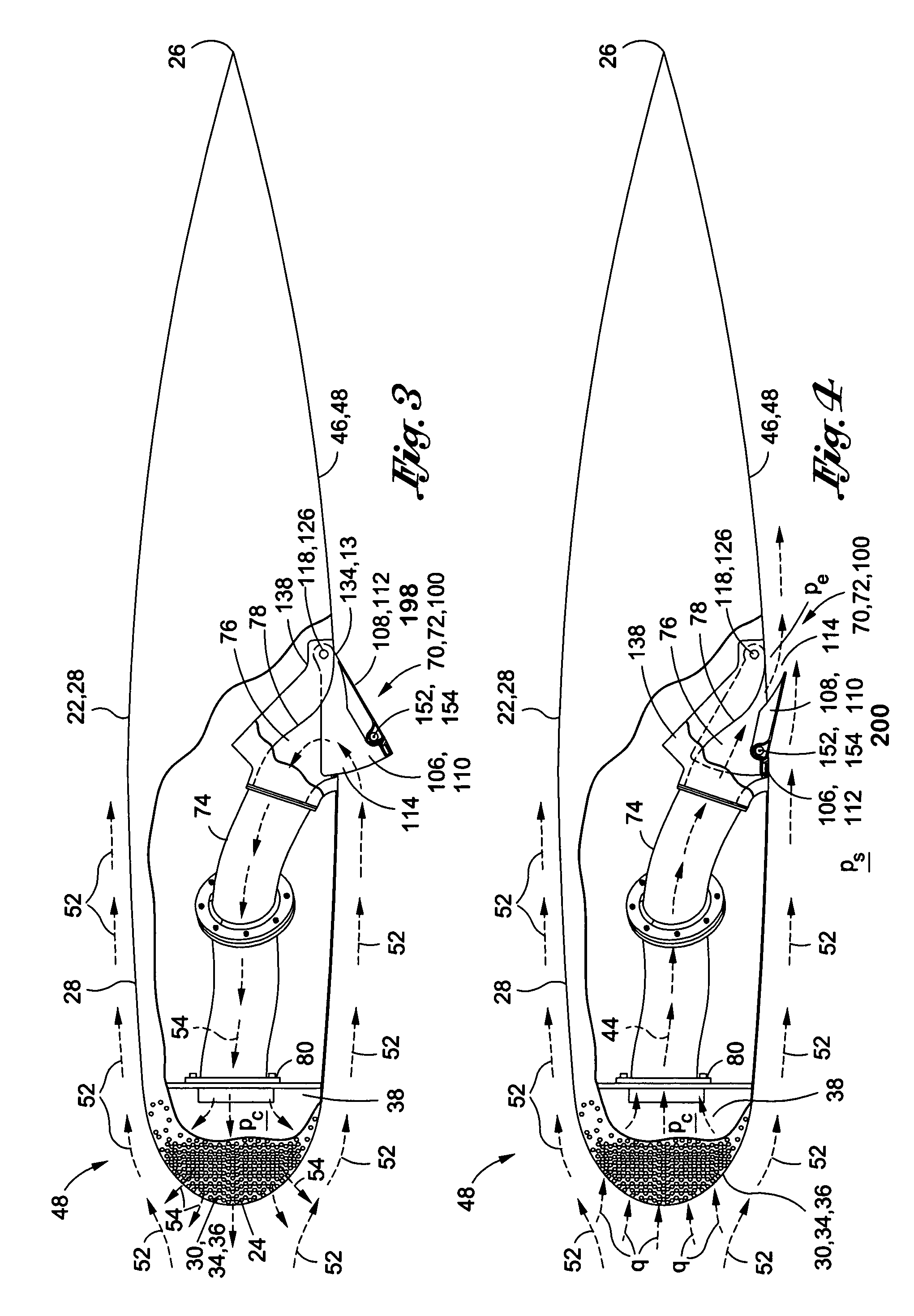
[0044]Referring now to the drawings wherein the showings are for purposes of illustrating preferred and various embodiments of the disclosure only and not for purposes of limiting the same, shown in FIGS. 1-19 is a door assembly 100 as may be used with a laminar flow control system 72. The door assembly 100 may include a first door 106 integrated with a second door 108. Advantageously, by combining the first and second doors 106, 108, the door assembly 100 provides a simple arrangement for passive purging and passive suctioning of a laminar flow control system 72.

[0045]As shown in FIGS. 6, 8 and 10, the first door 106 may include a first door cowl 116. The second door 108 may include a second door cowl 148 that may be pivotably mounted to the first door 106 and which may form at least a portion of the first door cowl 116. For example, as shown in the Figures, the second door cowl 148 may be configured to comprise a majority of the area of the first door cowl 116 although smaller rel...


PUM


Abstract

A door assembly has a first door integrated with a second door. The first door has a first door cowl. The second door is pivotably mounted to the first door and has a second door cowl forming at least a portion of the first door cowl. The door assembly includes at least one actuator coupled to the first and second doors. Each one of the first and second doors is pivotable between open and closed positions and defines an opening when moved to the open position. The openings of the first and second doors face in opposite directions. The actuator is operative to pivotably move at least one of the first and second doors between the open and closed positions.

Description

CROSS-REFERENCE TO RELATED APPLICATIONS[0001]This application is related to co-filed application Ser. No. 12 / 356,018 entitled APPARATUS AND METHOD FOR PASSIVE PURGING OF MICRO-PERFORATED AERODYNAMIC SURFACES filed on Jan. 19, 2009. This application is also related to application Ser. No. 11 / 763,569 entitled PASSIVE REMOVAL OF SUCTION AIR FOR LAMINAR FLOW CONTROL AND ASSOCIATED SYSTEMS AND METHODS filed on Jun. 15, 2007. The entire contents of the above-mentioned applications are expressly incorporated herein by reference.STATEMENT RE: FEDERALLY SPONSORED RESEARCH / DEVELOPMENT[0002](Not Applicable)FIELD[0003]The present disclosure relates generally to laminar flow control systems for aerodynamic surfaces and, more particularly, to a door assembly for passively suctioning and purging a laminar flow control system.BACKGROUND[0004]It is generally known that maintaining laminar flow of air passing over an airfoil can improve the aerodynamics and performance of an aircraft. For example, it...

Claims


Application Information

Patent Timeline
Patent Type & Authority Patents(United States)
IPC IPC(8): B64C1/14
CPCB64C21/02B64C21/08B64C2230/20Y02T50/166B64C2230/22B64D2241/00Y02T50/10B64C21/025
Inventor SAKURAI, SEIYAFEVERGEON, MATTHEW D.
Owner THE BOEING CO
Why Eureka
Try Eureka