Rotating printhead maintenance facility with symmetrical chassis
What is AI technical title?
AI technical title is built by Patsnap AI team. It summarizes the technical point description of the patent document.
a maintenance facility and printhead technology, applied in printing and other directions, can solve the problems of difficult wipes of pagewidth printheads, impractical for a single wiper to clean all the integrated circuits of printheads, and slow and/or complicated wiping mechanisms
Active Publication Date: 2012-08-21
SILVERBROOK RES PTY LTD +1
View PDF128 Cites 1 Cited by
Summary
Abstract
Description
Claims
Application Information
AI Technical Summary
This helps you quickly interpret patents by identifying the three key elements:
Problems solved by technology
Method used
Benefits of technology
Benefits of technology
The solution enables faster and more effective nozzle cleaning with consistent contact pressure, reducing the complexity and cost of maintenance while maintaining ink containment, thus improving the efficiency and reliability of pagewidth printhead maintenance.
Problems solved by technology
However, pagewidth printheads are difficult wipe.
While pagewidth printers with nozzle face wipers exist, the wiping mechanism is relatively slow and or complicated.
It is impractical for a single wiper to clean all the printhead integrated circuits, so each printhead integrated circuit is wiped individually.
In light of this, the mechanism that actuates the separate wipers for each printhead is complex, occupying a relatively large space and consuming a significant amount of time during each maintenance cycle.
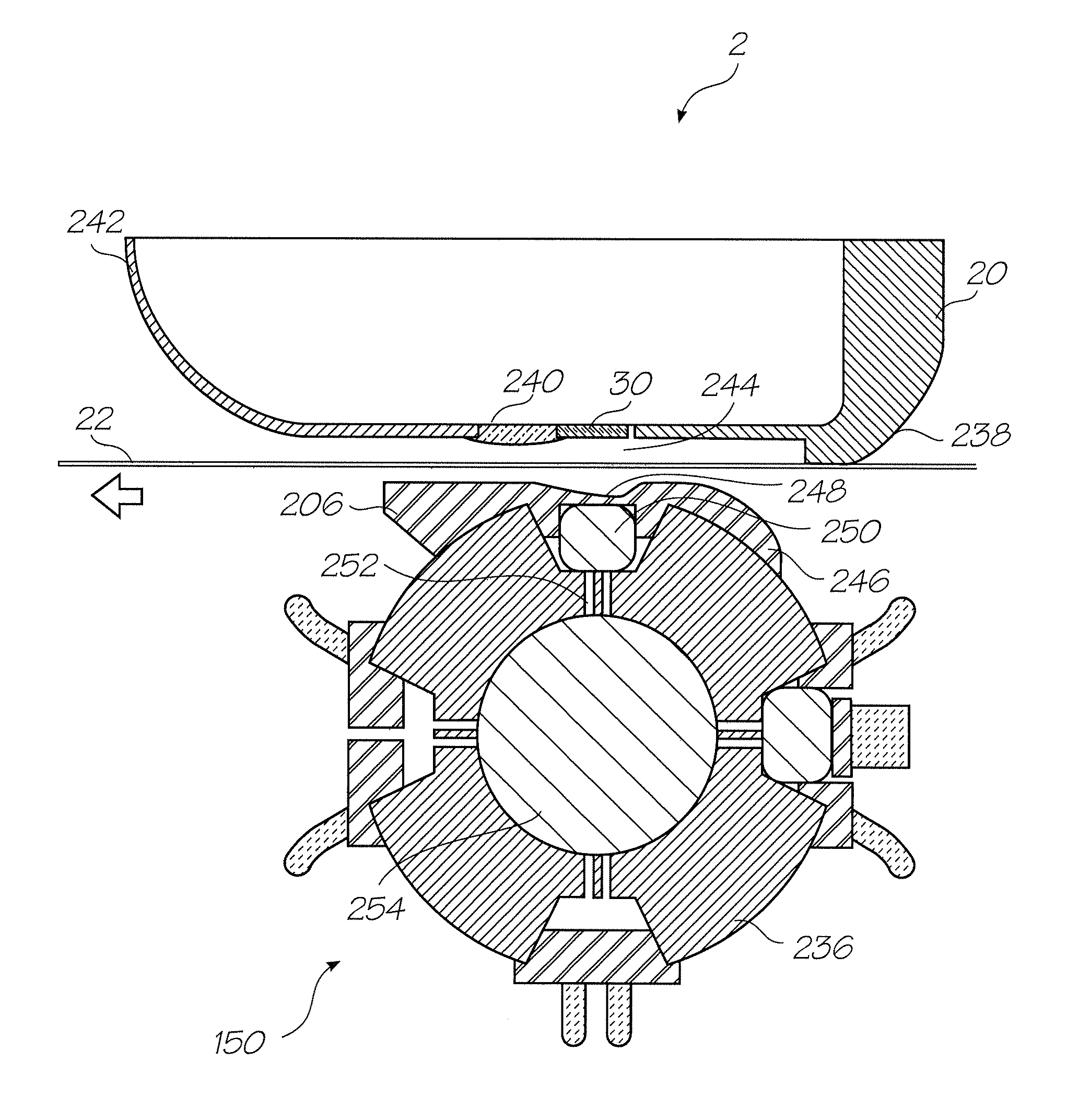
Another problem associated with wiping pagewidth printheads is the control of the contact force between the wiper and the nozzle face.
It will be appreciated that a non-uniform wiping force can damage the delicate nozzle structures wherever is two strong and fail to properly clean the nozzle face wherever it is too weak.
However, manufacturing a chassis structure with such fine tolerances typically requires the chassis to be a metal fabrication involving precision machining.
Method used
Image
Click on the blue label to locate the original text in one second.
Reading with bidirectional positioning of images and text.
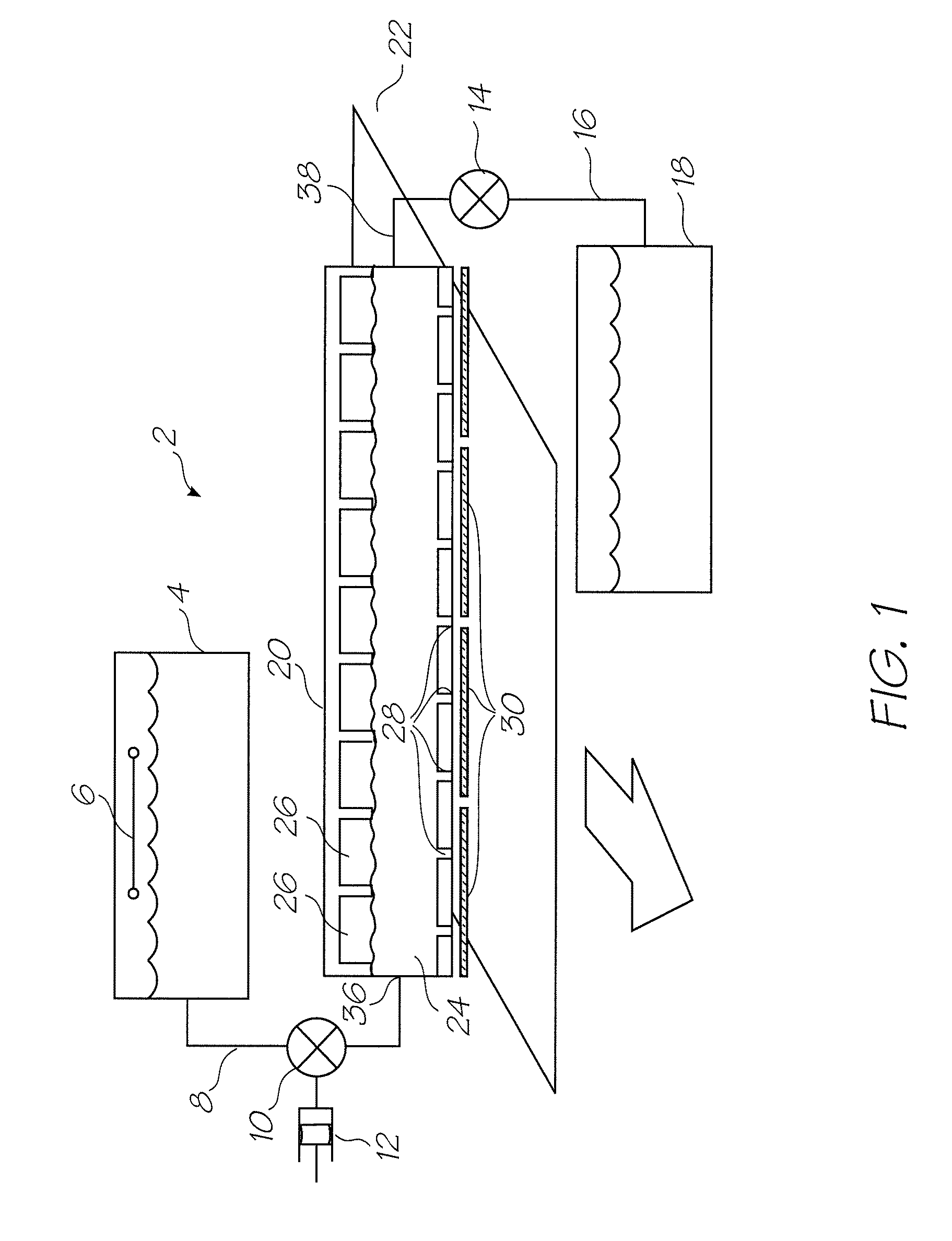
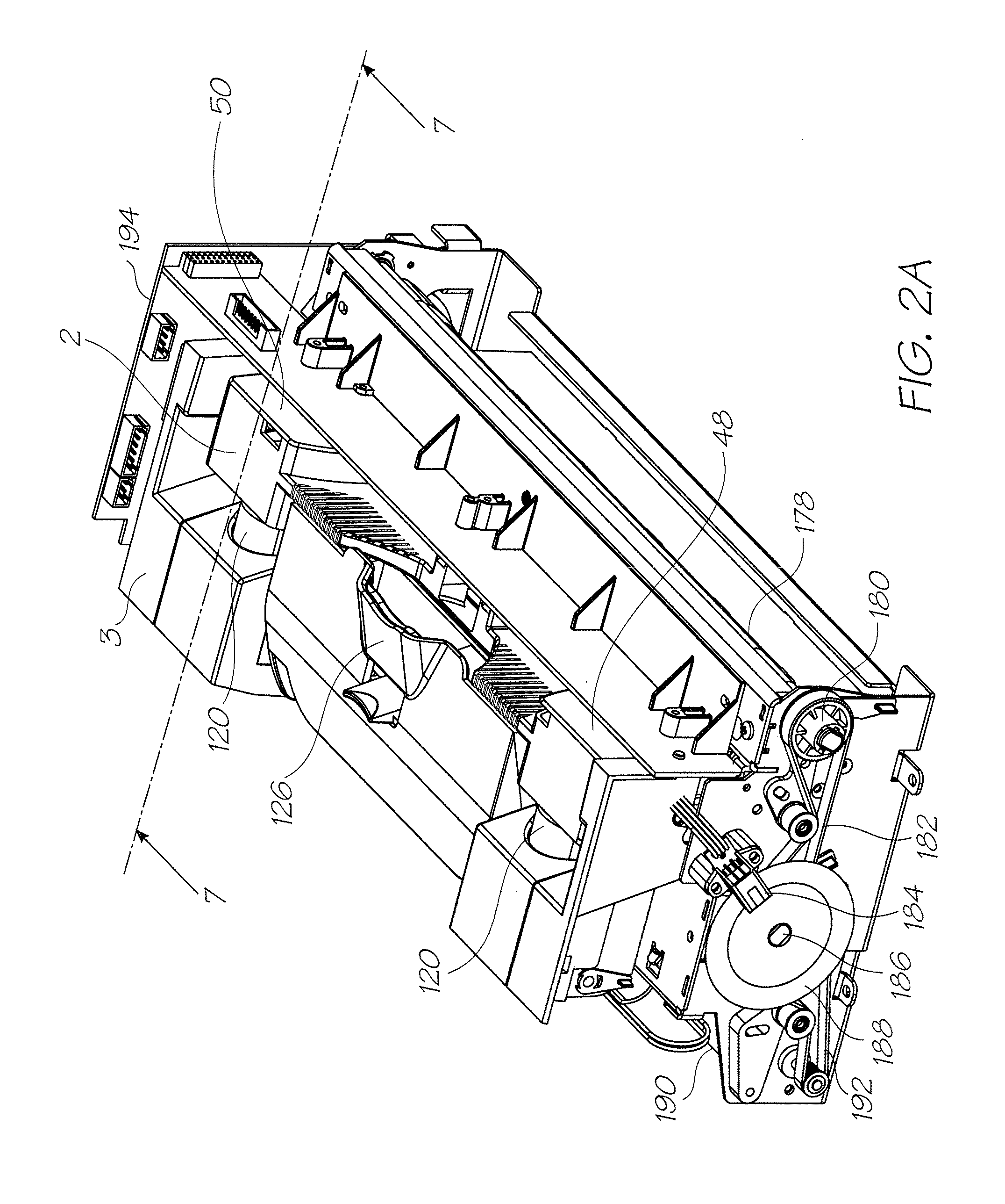
[0072]FIG. 1 is a schematic overview of the fluidic system used by the print engine described in FIGS. 2A and 2B. As previously discussed, the print engine has the key mechanical structures of an inkjet printer. The peripheral structures such as the outer casing, the paperfeed tray, paper collection tray and so on are configured to suit the specific printing requirements of the printer (for example, the photo printer, the network printer or Soho printer). The Applicant's photo printer disclosed in the co-pending application U.S. Ser. No. 11 / 688,863 is an example of an inkjet printer using a fluidic system according to FIG. 1. The contents of this disclosure are incorporated herein by reference. The operation of the system and its individual components are described in detail in U.S. Ser. No. 11 / 872,719 the contents of which are incorporated herein by reference.
[0073]Briefly, the printer fluidic system has a printhead assembly 2 supplied with ink from an ink tan...
PUM
Abstract
A maintenance facility for an inkjet printer with a pagewidth printhead and a media path for feeding sheets of media substrate in a media feed direction. The pagewidth printhead has an elongate array of nozzles extending the printing width of the media substrate and the maintenance facility has an elongate chassis for mounting in the printer such that it can rotate about its longitudinal axis and a plurality of maintenance stations mounted to an exterior surface of the elongate chassis. The elongate chassis is symmetrical about at least one plane extending through the longitudinal axis.
Description
FIELD OF THE INVENTION[0001]The present invention relates to be field of printers and in particular maintenance facilities for inkjet printheads.CO-PENDING APPLICATIONS[0002]The following applications have been filed by the Applicant simultaneously with the present application:[0003]12 / 014,76712 / 014,76812 / 014,76912 / 014,77012 / 014,7717,758,14912 / 014,7737,758,15212 / 014,7757,753,47712 / 014,77812 / 014,77912 / 014,78012 / 014,78112 / 014,78212 / 014,78312 / 014,78412 / 014,78512 / 014,7877,753,47812 / 014,78912 / 014,79012 / 014,7917,771,00212 / 014,7937,766,4517,771,00712 / 014,79812 / 014,80112 / 014,80312 / 014,80412 / 014,80512 / 014,80612 / 014,807[0004]The disclosures of these co-pending applications are incorporated herein by reference.CROSS REFERENCES[0005]The following patents or patent applications filed by the applicant or assignee of the present invention are hereby incorporated by cross-reference.[0006]6,276,8506,520,6316,158,9076,539,1806,270,1776,405,0556,628,4306,835,1356,626,5296,981,7697,125,3387,125,3377,13...
Claims
Application Information
Patent Timeline
Application Date:The date an application was filed.
Publication Date:The date a patent or application was officially published.
First Publication Date:The earliest publication date of a patent with the same application number.
Issue Date:Publication date of the patent grant document.
PCT Entry Date:The Entry date of PCT National Phase.
Estimated Expiry Date:The statutory expiry date of a patent right according to the Patent Law, and it is the longest term of protection that the patent right can achieve without the termination of the patent right due to other reasons(Term extension factor has been taken into account ).
Invalid Date:Actual expiry date is based on effective date or publication date of legal transaction data of invalid patent.
Patent Type & AuthorityPatents(United States)
IPC IPC(8): B41J2/165
CPCB41J2/16547B41J2/16585B41J2/16541
InventorHIBBARD, CHRISTOPHERMACKEY, PAUL IANTSUBONO, MAKOMOSILVERBROOK, KIA

