Gas turbine engine balancing

a gas turbine engine and rotor technology, applied in the direction of liquid fuel engines, vessel construction, marine propulsion, etc., can solve the problem of introducing stress concentrations on the rotor assembly

Active Publication Date: 2012-08-21
PRATT & WHITNEY CANADA CORP
View PDF18 Cites 30 Cited by
  • Summary
  • Abstract
  • Description
  • Claims
  • Application Information

AI Technical Summary

Benefits of technology

[0004]In one aspect, the described subject matter provides an apparatus for balancing a gas turbine engine rotor assembly, the apparatus comprising at least one annular balancing weight having a central aperture defined therethough, the at least one weight inserted into a cooling hole defined in the rotor assembly, the at least one balancing weight installed asymmetrically on the rotor assembly to thereby assist in balancing the rotor assembly.

Problems solved by technology

These configurations however, may introduce stress concentrations on the rotor assembly.

Method used


Image

  • Gas turbine engine balancing
  • Gas turbine engine balancing
  • Gas turbine engine balancing

Examples


Embodiment Construction

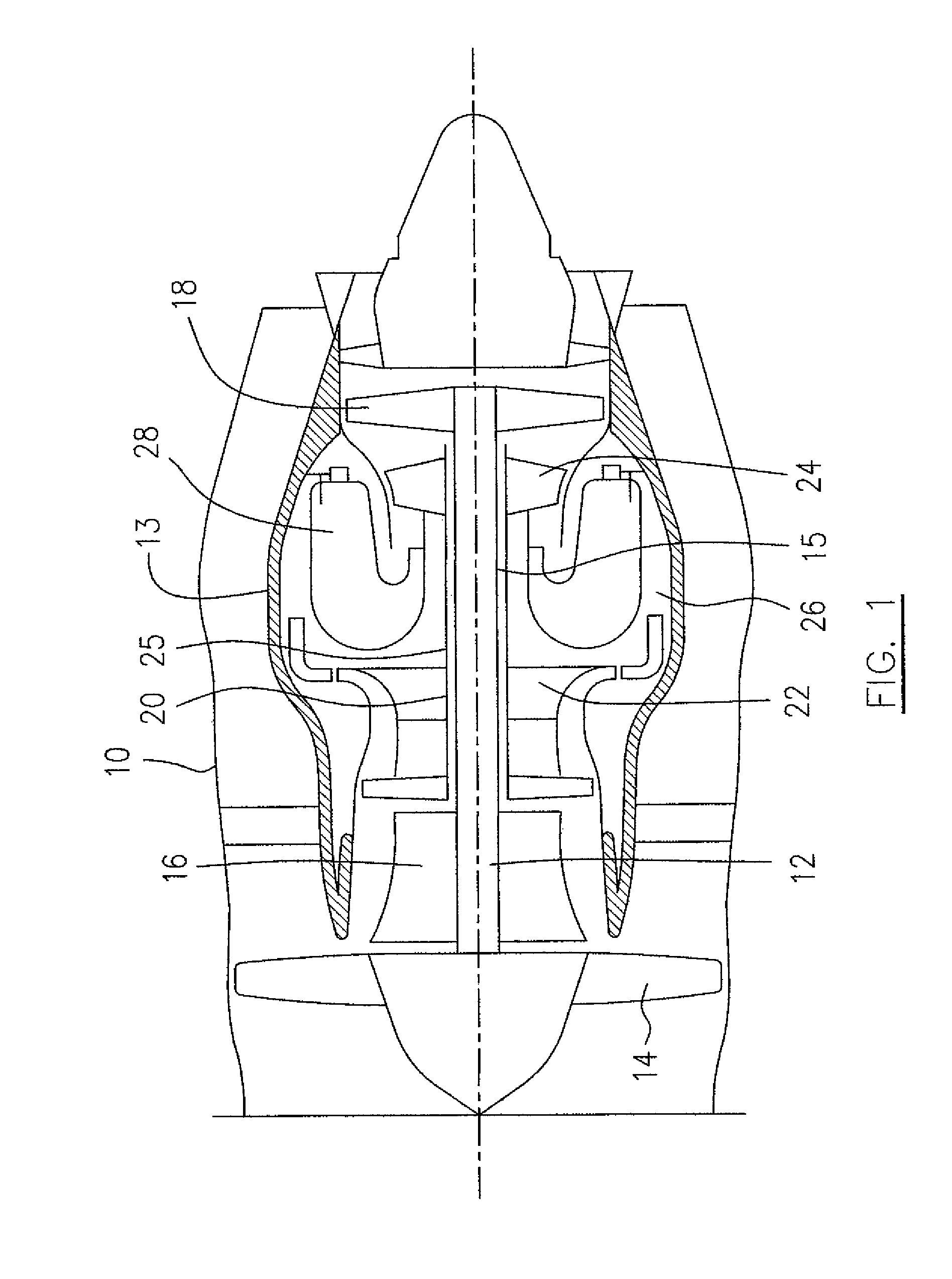
[0012]Referring to FIG. 1, a turbofan gas turbine engine incorporating an embodiment of the described subject matter is presented as an example of the application of the described subject matter, and includes a housing 10, a core casing 13, a low pressure spool assembly seen generally at 12 which includes a shaft 15 interconnecting a fan assembly 14, a low pressure compressor 16 and a low pressure turbine assembly 18 and a high pressure spool assembly seen generally at 20 which includes a shaft 25 interconnecting a high pressure compressor assembly 22 and a high pressure turbine assembly 24. The core casing 13 surrounds the low and high pressure spool assembly 12 and 20 in order to define a main fluid path (not numbered) therethrough. In the main fluid path there is provided a combustion section 26 having a combustor 28 therein.

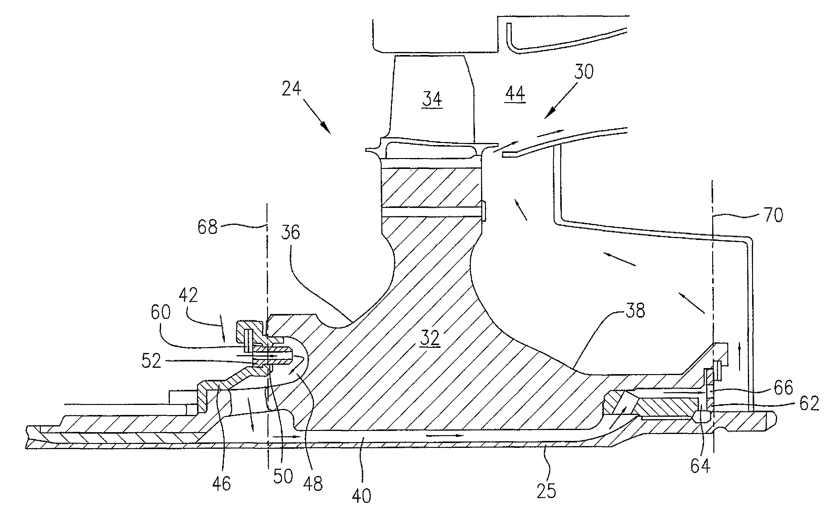
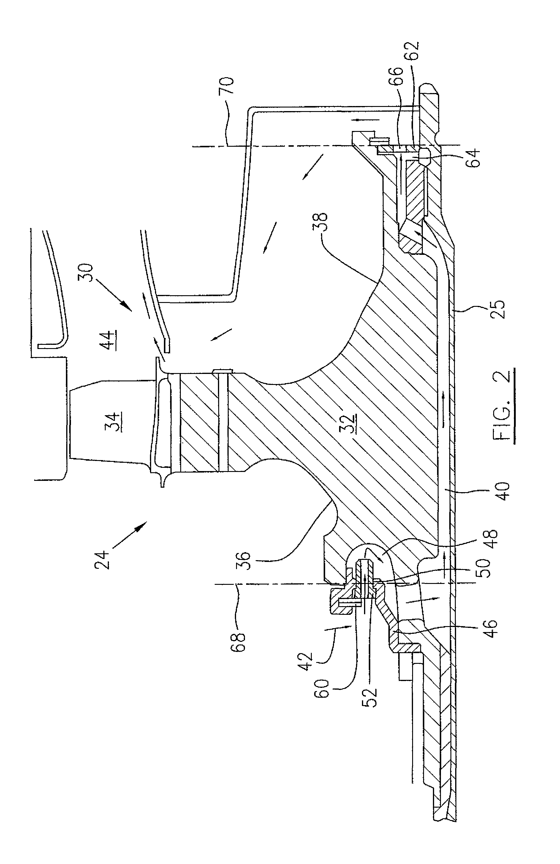
[0013]FIG. 2 shows, in cross-section, a rotor assembly 30 of the high pressure turbine assembly 24. The rotor assembly 30 includes a rotating disc 32 mounted...


PUM

PropertyMeasurementUnit
weightsaaaaaaaaaa
weightaaaaaaaaaa
balancing weightaaaaaaaaaa

Abstract

An apparatus and method for balancing a gas turbine engine rotor includes a plurality of balancing weights adapted to be selectively attached to at least one of inlets or outlets of a cooling passage of the rotor. The weights include cooling access which permits coolant to communicate with the cooling passage.

Description

TECHNICAL FIELD[0001]The subject matter relates generally to gas turbine engines, and more particularly, to balancing a gas turbine engine rotor.BACKGROUND OF THE ART[0002]A rotor assembly of a gas turbine engine may require balancing, for example, by addition of balancing weights in selected locations of the rotor assembly. Balancing weights are conventionally provided through dedicated attachments points on the rotor. These configurations however, may introduce stress concentrations on the rotor assembly.[0003]Accordingly, there is a need to provide for improved balancing or gas turbine engine rotors.SUMMARY OF THE INVENTION[0004]In one aspect, the described subject matter provides an apparatus for balancing a gas turbine engine rotor assembly, the apparatus comprising at least one annular balancing weight having a central aperture defined therethough, the at least one weight inserted into a cooling hole defined in the rotor assembly, the at least one balancing weight installed as...

Claims


Application Information

Patent Timeline
Patent Type & Authority Patents(United States)
IPC IPC(8): F01D5/08F01D5/10
CPCF01D5/027Y10T29/49316
Inventor LECUYER, DANIELCHATELOIS, BRUNODI PAOLA, FRANCO
Owner PRATT & WHITNEY CANADA CORP
Why Eureka
Try Eureka